DOCUMENTATION HANDBOOK PHONTECH CIS 3100 / 3101 / 3102 COMMAND INTERCOM SYSTEM.
|
|
|
- Marta Vigdis Kristiansen
- 8 år siden
- Visninger:
Transkript
1 DOCUMENTATION HANDBOOK PHONTECH CIS 3100 / 3101 / 3102 COMMAND INTERCOM SYSTEM

2 CIS 310X Handbook contents: SYSTEM / MASTER STATIONS: COMMAND INTERCOM SYSTEM 310X System Description DE. 3 Mechanical Layout, 3100, Master Station 5L ML Mechanical Layout, 3101, Master Station 10L ML Mechanical Layout, 3102, Master Station 20L ML External Connection, 3100, Master Station 5L EC External Connection, 3101, Master Station 10L EC External Connection, 3102, Master Station 20L EC Ver Handbook page: SYSTEM / MASTER STATION SUPPORT UNITS: 9014, GENERAL PURPOSE BACKUP POWER SUPPLY Mechanical Layout ML. 25 Internal wiring / External Connection IW , LINE AMPLIFIER Mechanical Layout ML. 27 Internal wiring / External Connection IW , BRIDGE WING MICROPHONE UNIT Mechanical Layout MD. 29 Internal wiring / External Connection IW , IN-BRIDGE WING UNIT Mechanical Layout ML. 31 Internal wiring / External Connection IW , BRIDGE WING PLUGBOX FOR MIC./L.S. Mechanical Layout ML. 33 External Connection EC.. 34 SUBSTATIONS: 9001, CABIN SUBSTATION Mechanical Layout ML. 35 External Connection EC , SUBSTATION FOR HEADSET Mechanical Layout ML. 37 External Connection EC , CALL UNIT Mechanical Layout ML. 39 External Connection EC , SUBSTATION FOR PORTABLE LOUDSPEAKER Mechanical Layout ML. 41 External Connection EC , PORTABLE LOUDSPEAKER w/bracket Mechanical Layout ML. 43 Internal wiring / External Connection IW , PLUGBOX WEATHERPROOF Mechanical Layout ML. 45 External Connection EC , SUBSTATION Mechanical Layout ML. 47 External Connection EC , HANDSET SUBSTATION w/relay Mechanical Layout ML. 49 Mechanical Layout (wall mounting) ML External Connection EC , SUBSTATION, WATERTIGHT Mechanical Layout ML. 52

3 External Connection EC.. 53 ACCESSORIES: 0005, HEADSET Mechanical Layout ML. 54 Internal wiring / External Connection IW , HANDHELD MICROPHONE w/plug Mechanical Layout ML. 56 Internal wiring / External Connection IW , 2 WAY MICROPHONE FOR BRIDGE WING Mechanical Layout ML. 58 Internal wiring / External Connection IW , WATERPROOF HAND-HELD MICROPHONE Mechanical Layout ML. 60 Internal wiring / External Connection IW.. 61 HP-10, HORN LOUDSPEAKER 10W, IP-56 Data Sheet HP-15, HORN LOUDSPEAKER 15W, IP-56 Data Sheet HP-20, HORN LOUDSPEAKER 20W, IP-67 Data Sheet EX SUBSTATIONS & ACCESSORIES: 9041, EX INTERFACE UNIT FOR SUBSTATIONS Mechanical Layout ML. 65 External Connection EC , EXTERNAL LOUDSPEAKER INTERFACE Mechanical Layout ML. 67 Internal wiring / External Connection IW.. 68 GHG-411, CALL UNIT (EX) Mechanical Layout DSP-15EExmN, EX HORN LOUDSPEAKER, IP-67 Data Sheet

4 3/71 Doc.No.: DE FINAL DOKUMENTATION CD REV No: ISSUE DATE REASON FOR ISSUE PREPARED CHECKED APPROVED TITLE: CIS SYSTEMS MASTER STATION SERIES 310X VERSION Description / Beskrivelse This document is the property of PHONTECH and must not be copied or shown to a third person without our written acceptance. In the interest of product improvement, PHONTECH reserves the right to alter specification and design without notice. SIZE: NA UED no: 94 DOC no: DE FILE NAME: DE.doc Page 1 of 16

5 4/71 Doc.No.: DE CONTENTS. 1.0 INTRODUCTION / INTRODUKSJON 2.0 GENERAL DESCRIPTION / GENERELL BESKRIVELSE 3.0 FACILITY LIST / FUNKSJONER OG MULIGHETER 4.0 MOUNTING / INSTALLATION / SCREEN CONNECTION. MONTERING / INSTALLASJON OG SKJERM TERMINERING 5.0 CABLE REQUIREMENTS / KRAV TIL KABEL 6.0 SELECTIVE CALLS / SELEKTIVE ANROP 7.0 ALL CALL / ALLEKALL(FELLESANROP) 8.0 BRIDGE WING - EXTERNAL PAGING BROVING - EKSTERNT AKTIVERT ANROP 9.0 PRIORITY / PRIORITET 10.0 CALLS DURING AN EXTERNAL ALL-CALL ANROP UNDER EKSTERNT ALLEKALL 11.0 INTENTIONALLY LEFT OUT / UTELATT 12.0 INTENTIONALLY LEFT OUT / UTELATT 13.0 TECHNICAL DATA / TEKNISKE DATA 14.0 SYSTEM BOARD (CIS 3100/3101) STRAPPING AND CONNECTION POINT LOCATIONS. LOKALISERING AV LINKER OG KONTAKTPUNKTER 15.0 SYSTEM BOARD (CIS 3102) STRAPPING AND CONNECTION POINTS LOCATION. LOKALISERING AV LINKER OG KONTAKTPUNKTER Page 2 of 16
 STRAPPING AND CONNECTION POINT LOCATIONS.")
6 5/71 Doc.No.: DE 1.0 INTRODUCTION / INTRODUKSJON Eng.: A command intercom system (CIS) consist of one MASTER station (3100 series), most often located on the ships bridge, and distributed SUBSTATIONS (9000 series) in cabins, engine room, engine control room a.s.o. The CIS may also comprise port and starboard side BRIDGE WING stations. The CIS may also be interconnected with the PHONTECH small public address and alarm system (SPA). The CIS serves as two-way command and intercom system. The communication channels is to/from the master station and the substations. Please note that communication between the substations is not possible. The compact design makes the CIS easy to install. The mounting is for 3100/3101 DIN 144 x 144mm, 3102 DIN 192 x 144 mm. flush mounting, or wall mounting. (wallmount backbox required) No.: Et kommando intercom system (CIS) består av en MASTER stasjon (3100 serie), som oftest plassert på båtens bro, og distribuerte understasjoner (9000 serie) i lugarer, motorrom, motor kontrollrom osv. CIS kan også omfatte babord og styrbord broving stasjoner. Systemet kan også tilkobles til PHONTECH "small public address and alarm system" (SPA). CIS tjener som et to-veis kommando kommunikasjonssystem, med oppkallsmulighet begge veier. Kommunikasjonen går mellom master og understasjoner, dvs. at kommunikasjon mellom understasjoner ikke er mulig. Det kompakte designet gjør systemet lett å installere. Montering er for 3100/3101 DIN 144 x 144mm, 3102 DIN 192 x 144 mm. innfelt montering eller på vegg montasje. ting. Veggmontering krever ekstra bakboks som er ekstrautstyr. 2.0 GENERAL DESCRIPTION / GENERELL BESKRIVELSE Eng.: The CIS is delivered as follows: No.: MASTER STATIONS CIS MASTER STATION max. 5 extensions. Amplifier capacity 10W CIS MASTER STATION max. 10 extensions. Amplifier capacity 20W CIS MASTER STATION max. 20 extensions. Amplifier capacity 40W. SUBSTATIONS, ACCESSORIES substation for cabins and/or accommodation areas substation for headset with relay call unit for loudspeaker, weatherproof call unit for portable loudspeaker, weatherproof plug box, weatherproof call unit for loudspeaker, loudspeaker on/off switch, weatherproof engine control room phone. (handset) headset 10 m. cable and plug additional handset portable loudspeaker cable and plug gooseneck microphone unit, PTT, flush mounting microphone box, bridge wing connection hand microphone cable and plug line amplifier. The MASTER stations contains the electronics required in an CIS. As an extended value added feature, the CIS 310X units are supplied with a "loudspeaker as substation / automatic call disable" facility. This makes the installer able to connect plain loudspeakers directly as substations. During power on the CIS 310X unit will detect such configurations and prevent calls from this positions. Page 3 of 16

7 6/71 Doc.No.: DE CIS leveres som følger: MASTER STASJONER: CIS MASTER STASJON maks. 5 linjer. Forsterker kapasitet 10 W CIS MASTER STASJON. maks. 10 linjer. Forsterker kapasitet 20 W CIS MASTER STASJON. maks. 20 linjer. Forsterker kapasitet 40 W. UNDERSTASJONER/UTSTYR: understasjon for lugar/ oppholdsrom understasjon for hodesett med rele oppkallsenhet for høyttaler, værsikker kalleenhet for bærbar høyttaler, værsikker plugg boks værsikker kalleenhet for høyttaler, høyttaler bryter, værsikker maskinkontroll rom telefon. (håndsett) hodesett med 10m kabel og plugg ekstra handsett bærbar høyttaler,med kabel og plugg svanehals mikrofon enhet, tal knapp, innfelt montering mikrofonboks for broving tilkobling håndmikrofon med kabel og plugg linjeforsterker. MASTER stasjonene inneholder stort sett all elektronikken som kreves i et CIS system. I tillegg er alle CIS 310X enheter utstyrt med funksjonen "høyttaler som understasjon / automatisk oppkalls-hindring. Dette gir installatøren mulighet til å tilkoble høyttalere direkte til understasjon linjer. Ved påslag vil CIS 310X enheten oppdage dette og i ettertiden hindre oppkall fra disse posisjonene. 3.0 FACILITY LIST Eng.: (see figure 1) CIS 3100: - Connection for 5 substation lines. CIS 3101: - Connection for 10 substation lines. CIS 3102: - Connection for 20 substation lines. COMMON: - Loudspeaker as substation / automatic call disable - Connection for port and starboard bridge wing stations. - Connection for phontech SPA system. - Built-in wide-band loudspeaker. - Built- in condenser microphone. - Automatic gain control for speech level. - Loudspeaker volume control - Bi-coloured key indicator leds. - Call key. - Talk key. - Automatic all call function. - Extra signal organ output for line 1-4. Page 4 of 16
 - 0005 hodesett med 10m kabel og plugg. - 0006 ekstra handsett.")
8 7/71 Doc.No.: DE - External loudspeaker output connections. OPTIONS. - Line engagement time out. - Optional extra signal organ output for all lines (up to 10) - Optional line amplifier connection. - Gooseneck/handheld microphone connection. No.: CIS 3100: - Tilkobling for 5 understasjoner. CIS 3101: - Tilkobling for 10 understasjoner. CIS 3102: - Tilkobling for 20 understasjoner. FELLES: - Høyttaler som biapparat / automatisk oppkalls-hindring - Tilkobling for babord og styrbord broving stasjoner. - Tilpasset for sammenkobling med phontech SPA system. - Innebygget bredbånds høyttaler. - Innebygget kondensator mikrofon. - Automatisk nivå kontroll krets for tale. - Høyttaler volum kontroll. - To-fargede linje indikasjons lysdioder. - Kalle tast. - Tale tast. - Automatisk allekall funksjon. - Ekstra signal giver utgang for linje Ekstern høyttaler utgang. VALGBART: - Automatisk tidsstyrt linje nedkobling - Ekstra signal utgang for alle linjer. (opp til 10) - Linje forsterker tilkobling. - Svanehals /håndmikrofon tilkobling Page 5 of 16

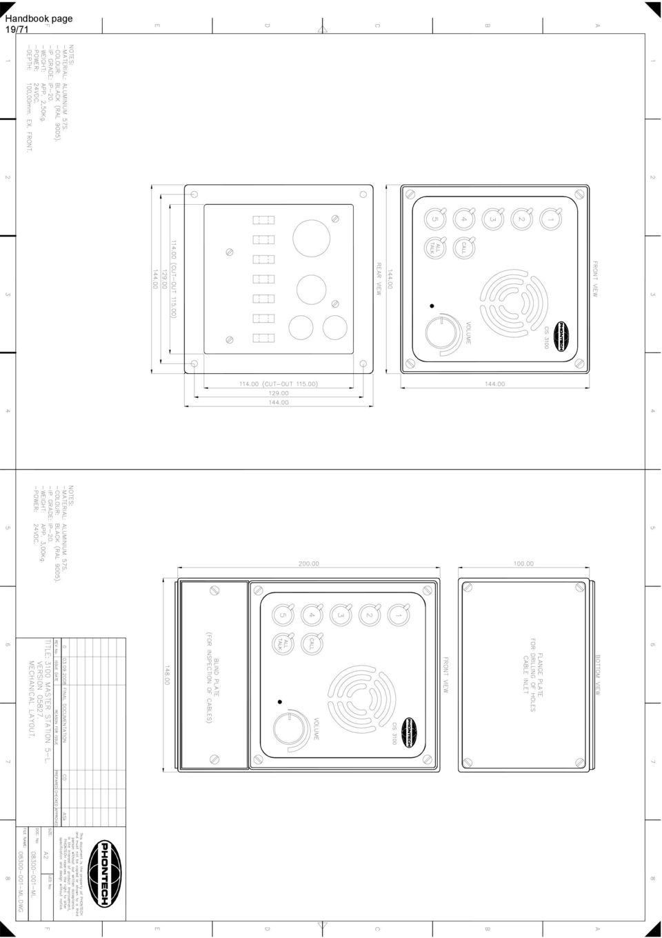
9 8/71 Doc.No.: DE FIGURE 1 / FIGUR MOUNTING / INSTALLATION / SCREEN CONNECTION MONTERING / INSTALLASJON OG SKJERMTERMINERING Eng.: MOUNTING: The master stations 3100/3101/3102 is delivered for flush mounting. On request the units may be delivered with wall-mounting box. (option) Front plate dimensions 3100 and 3101: 144 x 144 mm. (HxW) 3102: 144 x 192 mm. (HxW) Cut- out dimensions for flush-mounting 3100 and 3101: 115 x 115 mm. (HxW) 3102: 115 x 163 mm. (HxW) Depth, all types flush mounted: 100 mm. wall mounted: 100 mm. INSTALLATION: The installation should be planned in details before starting. The cables should be listed in a cable plan, with number of pairs a.s.o. The location of each unit in the intercom system should be planned to obtain maximum performance and user ability. Page 6 of 16
 Depth, all types flush mounted: 100 mm. wall mounted: 100 mm. INSTALLATION: The installation should be planned in details before starting.")
10 9/71 Doc.No.: DE The master station location/ orientation with regards to the operator must be taken especially into consideration. Please note the gooseneck mic (if installed) is "close talk". A close talk microphone has the ability to reduce surrounding noise to a minimum. The drawback is that the operator has to speak no more than 5-10 cm away from the microphone. SCREEN CONNECTION. In order to obtain maximum performance after installation, it is necessary to terminate the cables and ground the screens in a good manners. The cables is to be de-isolated by removing approximately 250 mm of the outer insulation. Then the screen braid is cut off appr. 30 mm longer than the outer isolation. The conductors is de-isolated and fitted with endcrimps before they are inserted into the terminal. The outer screen is clamped to the cable fixing arcs inside the cabinet. Cable ties of a conductive type is recommended for best result. Please see figure 2 for more details. No.: Hoved stasjonene 3100/3101/3102 leveres som standard for innfelt montering. På forespørsel kan veggboks leveres for utvendig montering Front plate dimensjoner 3100 and 3101: 144 x 144 mm. (HxB) 3102: 144 x 192 mm. (HxB) Utstansingsmål for innfelt montering, 3100 and 3101: 115 x 115 mm. (HxB) 3102: 115 x 163 mm. (HxB) Dybde, alle typer innfelt montering: 100 mm. utvendig montering: 100 mm. INSTALLASJON: Installasjonen bør planlegges i detalj før start. Kablene bør listes i en kabel plan med nummererte par etc. Plasseringen av hver enhet i intercom systemet bør kartlegges for å oppnå maksimal bruksvennlighet og ytelse. Det bør legges spesiell vekt på plassering av hovedstasjon i forhold til operatøren. Viktig å vite er at dersom det installeres en svanehals mikrofon (gooseneck microphone) er denne ofte "close-talk", dvs. med direktiv virkning. En direktiv mikrofon har den fordel at den er lite følsom for omgivelsesstøy. Ulempen er at operatøren må svært nær for å tale (5-10 cm). SKJERM TERMINERING: For å oppnå maksimal lydkvalitet er det meget viktig med god og riktig terminering av skjerm. Kablene skal avisoleres ved å fjerne den yttre beskyttelses kappen i en lengde på ca 250mm. Deretter kuttes ytterskjermen slik at denne stikker ca. 30 mm ut fra kabelisolasjonen. Lederne avisoleres og helst påmonteres termineringshylser for å oppnå best og varig kontakt i skruterminalene. Ytterskjermen klemmes inntil de dertil egnede feste punktene på innsiden av bakboksen. For å oppnå best kontakt bør festebånd av elektrisk ledende materiale benyttes. Ref. figur 2 for detaljer Page 7 of 16

11 10/71 Doc.No.: DE FIGURE 2 / FIGUR 2 Eng.: The cable outer screens is to be terminated as shown. Conductive type of cable ties is recommended to obtain best possible screen connections. No.: Kabelens ytterskjerm skal termineres som vist. Festebånd av ledende materiale bør benyttes for å oppnå best kontakt mellom skjerm og chassis. 5.0 CABLE REQUIREMENTS / KRAV TIL KABEL Eng.: To substations: one pair, twisted, outer screen. If extra signal organ: one pair extra. To bridge wings: two pairs, individually twisted, outer screen. Power cables: one pair, gnd. Minimum conductor area all cable types: 0.75 mm 2. IMPORTANT: TO SECURE UN-INTERFERED OPERATION DO NOT COMBINE SIGNAL CABLES WITH OTHER CABLE TYPES SUCH AS MAINS SUPPLY. THE CABLING FOR THE CIS SYSTEM SHOULD BE A SEPARATE NETWORK. Page 8 of 16

12 11/71 Doc.No.: DE Consult drawings EC (CIS 3100), EC (CIS 3101) and EC (CIS 3102) for further cabling information. No.: Til understasjoner: ett par revolvert, utvendig skjermet. Ved ekstra signal organ: et ekstra par. Til broving: to par, individuelt revolvert, utvendig skjerm. Kraft kabler: ett par, jord. Minimum tverrsnitt alle typer: 0,75 mm 2. VIKTIG: FOR Å SIKRE UFORSTYRRET DRIFT, IKKE KOMBINER SIGNAL KABLER MED KABLER FOR ANNET UTSTYR SOM F.EKS. NETTKABLER OSV. KABLINGEN FOR CIS SYSTEMET SKAL VÆRE ET EGET NETT. I dokumentene EC (CIS 3100), EC (CIS 3101) og EC (CIS 3102) finnes ytterligere informasjon SELECTIVE CALLS / SELEKTIVE ANROP Eng.: This chapter describes the operation of the CIS master stations. In idle status / after power-up, the master station line indicator leds illuminates dim green as night orientation light. No.: Dette kapittelet beskriver bruken av hovedstasjonene. I hvilestilling og etter påslag lyser hovedstasjonens lysdioder svakt grønt. (bakbelysning) 6.1. MASTER CALL TO A SUBSTATION / HOVEDSTASJON ANROPER UNDERSTASJON Eng.: - Select the line by operating the appropriate line key. The line indicator led turns red. - Now press the CALL key. This will generate an attention tone in the substation unit loudspeaker and activate the extra signal device if any. Note: several lines may be called simultaneously. No.: - Velg ønsket linje ved å trykke inn linjeknappen. Linje indikator lysdiode skifter til rødt fullt lys. - Trykk CALL knappen. Dette starter en oppmerksomhetstone i understasjonens høyttaler/ hodesett. Eventuelt ekstra signal organ starter også. NB: flere linjer kan kalles samtidig MASTER CALL TO ALL SUBSTATIONS / HOVEDSTASJON ANROPER ALLE UNDERSTASJONER Eng.: - Press the ALL/TALK key without any lines engaged. The master station automatically enters the all-call mode. All the leds illuminates red colour. -Speak into the microphone. No.: - Trykk ALL/TALK knappen uten noen linjer aktive. Hovedstasjonen velger automatisk alle-kall modus. Alle lysdiodene tenner rødt lys, også lysdiode for ALL/TALK knappen. -Snakk direkte inn i mikrofonen. Page 9 of 16
, 97301-002-EC (CIS 3101) og 97301-013-EC (CIS 3102) finnes ytterligere informasjon. 6.0. SELECTIVE CALLS / SELEKTIVE ANROP Eng.")
13 12/71 Doc.No.: DE 6.3 A SUBSTATION ANSWER THE CALL FROM THE MASTER / UNDERSTASJONEN SVARER PÅ ANROP FRA HOVEDSTASJON Eng.: When the attention tone is heard in the loudspeaker and / or the extra signal organ is activated: - Press the talk-key and answer the call. - Keep the TALK key pressed all time during the conversation. No.: Når oppmerksomhetstonen høres i høyttaleren / eller ekstra signal giver aktiveres: - Trykk på TALK knappen for å svare oppkallet. - Hold TALK knappen inne hele tiden mens samtalen pågår THE MASTER TALKING TO THE SUBSTATION / HOVEDSTASJONEN SNAKKER TIL EN UNDERSTASJON Eng.: When the call is answered: - Operate the TALK key on the master and talk into the microphone / loudspeaker. - Release the talk-key to return to listen-mode. No.: Når understasjonen svarer oppkallet: - Trykk TALK knappen og snakk inn i mikrofonen / høyttaleren. - Slipp TALK knappen for å returnere til lytte-modus SUBSTATION CALL TO MASTER / UNDERSTASJON OPPKALL TIL HOVEDSTASJON Eng.: - Press the CALL button on the substation / call unit. This generates an attention tone in the master station as long as the call-button is kept pressed. Simultaneously the appropriate line indicator led turns full light green to indicate which substation made the call. Note: If a call occurs during an on-going conversation, the attention tone is disabled, but the line indicator led change to green colour full intensity. No.: - Trykk på CALL knappen på understasjonen. Dette starter oppkallstonen i hovedstasjonen, og denne lyder så lenge understasjonen prøver å kalle opp. Samtidig tenner linjens lysdiode grønn, fullt lys, for å indikere hvilken understasjon som kaller. Viktig: hvis et oppkall inntreffer under pågående samtale, aktiveres ikke kalletonen, men lysdioden tenner fullt grønt lys THE MASTER ANSWER THE CALL FROM A SUBSTATION / HOVEDSTASJONEN SVARER PÅ ANROP FRA UNDERSTASJONEN Eng.: To answer the call from a substation: - Press the appropriate line key. The line indicator led turns green full intensity. - Press the talk key and speak into the microphone. - Release the TALK key to return to listen mode. No.: For å svare et oppkall fra en understasjon. - Trykk inn gjeldende linjeknapp. Lysdioden tenner fullt rødt lys. - Trykk inn TALK knappen og snakk inn i mikrofonen. - Slipp TALK knappen for å returnere til lytte-modus. Page 10 of 16

14 13/ TERMINATING THE CONVERSATION / AVSLUTTE SAMTALEN Eng.: The conversation is terminated by de-activating the line: - Operate the line key once more. The line indicator led turn green half-light intensity. (backlight) No.: Samtalen avsluttes ved å legge linjen ut igjen: - Trykk linjeknappen en gang til. Lysdioden skifter til grønt baklys (hvilestilling). Doc.No.: DE 7.0. ALL CALL / ALLEKALL Eng.: The master station CIS 3100/3101/3102 may perform an ALL CALL to the substations. - Operate the ALL/TALK key. (no lines active) A special attention tone (1kHz chopped) is distributed to all the substations for about 2-3 seconds. Simultaneously all the extra signal organ outputs is activated for 2-3 seconds. All the line indicator leds turns red colour. The call key indicator led illuminate red during this interval (2-3 seconds.) When this led turns off again the system is ready to use. - Give the message and release the ALL/TALK key. No.: Hovedstasjonene CIS 3100/3101/3102 kan utføre alle kall til understasjonene. - Trykk inn ALL/TALK knappen når hovedstasjonen er i hvilestilling (ingen linjer aktivert). En spesiell tone 1kHz pulset (viktig melding), distribueres til alle understasjonene i cirka. 2-3 sekunder. Samtidig aktiveres alle ekstra signal utganger i cirka 2-3 sekunder. Alle linje indikator lysdioder tenner rødt. Call knappens lysdiode tenner rødt i 2-3 sekunder. Når CALL knappens lysdiode slukker er systemet klart til bruk. - Snakk inn i mikrofonen og slipp TALK knappen etter meldingen. 8.0 BRIDGE WING - EXTERNAL PAGING / BROVING - EKSTERNT AKTIVERT ANROP Eng.: Two separate external audio and key lines are provided for remote paging. These interfaces are as default intended for bridge wing paging, port and starboard. In this mode they interface a loudspeaker/microphone/key configuration. The paging can be done in 2 ways. Either prepared in advance on the master station making the bridge wing able to communicate with the selected substations (conversation mode). Or the system can be keyed directly from idle into the all call paging mode. In both situations the master station loudspeaker will relay the activity. The starboard bridge wing interface has an alternative mode; the emergency allcall mode. It can be redefined as an interface to other equipment (Phontech SPA 1500 system) or be activated from an emergency microphone position. In the emergency all call mode it will generate an ALL CALL situation independent of prior status (idle or busy) (Ref. chapter 9 - priority and chapter 14 or 15 - Strapping and connection point locations). Both speech audio and alarms may be fed to this input. No.: To separate eksterne audio og nøklings linjer er tilgjengelig for fjernstyring av anrop. Disse linjene er primært ment brukt til anrop fra broving, babord og styrbord. Linjene interfacer en høyttaler/mikrofon/nøklings konfigurasjon. Anropet kan gjøres på 2 måter. Enten kan et linjevalg settes opp i forkant. På denne måten kan brovingene samtale med understasjonene i begge retninger (konversasjons modus). Eller systemet kan nøkles direkte fra hvilesituasjon til allekall/fellesanrop. I begge tilfelle vil hovedstasjonens høyttaler monitorere samtale begge veier. Styrbord broving linje kan omdefineres til en nød allekall modus. Linjen kan omdefineres for tilkobling enten til annet utstyr (Phontech SPA 1500 system) eller den kan aktiveres fra en nødmikrofon. I nød allekall modus vil systemet generere et allekall/fellesanrop uansett status på forhånd (ledig/opptatt). (ref. kapittel 9 - Prioritet og kapittel 14 eller 15 - Lokalisering av linker og kontaktpunkter). Både tale og alarmtoner kan tilføres denne linjen. 9.0 PRIORITY / PRIORITET Eng.: Page 11 of 16
 A special attention tone (1kHz chopped) is distributed to all the substations for about 2-3 seconds.")
15 14/71 Doc.No.: DE - The master station normally has first priority. - If the external emergency paging is enabled this will have an intermediate first priority and override existing calls. After this first priority override activation the master station regains priority and can place calls of any type. No.: - Hovedstasjonen har normalt første prioritet. - Dersom eksternt nød allekall aktiveres vil dette likevel ha midlertidig første prioritet og overstyre eventuelle eksisterende anrop. Etter første gangs aktivering vil hovedstasjonen gjenerobre første prioritet og kan gjøre anrop av alle typer CALLS DURING AN EXTERNAL ALL-CALL / ANROP UNDER EKSTERNT ALLEKALL Eng.: Line selections during emergency all call (press any substation line key even if this is already busy (led indicator) causes all other lines to disable and a two-way conversation can be made. Alternatively the talk key can be activated immediately causing substation audio to be replaced by the master station message. When the talk key is released, the external emergency all call will be re-engaged. No.: Dersom linjer velges under et eksternt nød allekall (aktiver understasjon linjer selv om linjeindikatoren lyser rødt) vil de øvrige linjene deaktiveres slik at en to-veis samtale med valgt linje fan skje. Alternativt kan hovedapparat operatøren trykke TALK direkte og erstatte understasjon audio med egen melding. Når TALK tasten slippes gjeninnføres det eksterne nød allekall INTENTIONALLY LEFT OUT / UTELATT 12.0 INTENTIONALLY LEFT OUT / UTELATT 13.0 TECHNICAL DATA. CIS Operation voltage / driftsspenning: Current drain / strømtrekk: Line capacity / linjekapasitet: Power amp. capacity / forsterkerkapasitet: Frequency range / frekvens område: Distortion / forvrengning: Extra signal organ output / ekstra signal giver utgang: Bridge wing microphone input / Broving mikrofon nivå: Bridge wing loudspeaker output / Broving høyttaler utgang: Line level, Stb. Bridge wing Emergency paging level / Linje nivå, Styrbord broving Nød melding nivå: 24 VDC 1 A max. 5 lines. 10 W total Up to 10 W per line. Better than Hz (-3dB) Better than 2.5% typ VDC, max 150mA Open collector output to GND 200 Ohm / 10 mv typ. 8 Ohm / 5W typ. 775 mv (0dBm) typ. CIS Operation voltage / driftsspenning: 24 VDC Page 12 of 16

16 15/71 Doc.No.: DE Current drain / strømtrekk: Line capacity / linjekapasitet: Power amp. capacity / forsterkerkapasitet: Frequency range / frekvens område: Distortion / forvrengning: Extra signal organ output / ekstra signal giver utgang: Bridge wing microphone input / Broving mikrofon nivå: Bridge wing loudspeaker output / Broving høyttaler utgang: Line level, Stb. Bridge wing Emergency paging level / Linje nivå, Styrbord broving Nød melding nivå: CIS 3102 Operation voltage / driftsspenning: Current drain / strømtrekk: Line capacity / linjekapasitet: Power amp. capacity / forsterkerkapasitet: Frequency range / frekvens område: Distortion / forvrengning: Extra signal organ output / ekstra signal giver utgang: Bridge wing microphone input / Broving mikrofon nivå: Bridge wing loudspeaker output / Broving høyttaler utgang: Line level, Stb. Bridge wing Emergency paging level / Linje nivå, Styrbord broving Nød melding nivå: 2 A max. 10 lines. 20 W total Up to 10 W per line. Better than Hz (-3dB) Better than 2.5% typ VDC, max 150mA Open collector output to GND 200 Ohm / 10 mv typ. 8 Ohm / 5W typ. 775 mv (0dBm) typ. 24 VDC 3 A max. 20 lines. 40 W total Up to 10 W per line. Better than Hz (-3dB) Better than 2.5% typ VDC, max 150mA Open collector output to GND 200 Ohm / 10 mv typ. 8 Ohm / 5W typ. 775 mv (0dBm) typ. Page 13 of 16

17 16/71 Doc.No.: DE 14.0 SYSTEM BOARD (CIS 3100/3101) STRAPPING AND CONNECTION POINT LOCATIONS / LOKALISERING AV LINKER OG KONTAKTPUNKTER. J2 Terminal / pin No. - J2 Terminal / pin. nr. Function / Equipment Funksjon / tilkoblet utstyr 1 & 2 Volume potensiometer Volum potensiometer 3 & 4 Unit loudspeaker Apparat høyttaler 5 & 6 Microphone Mikrofon element 7 & 8 TALK activator Tale knapp Strap ST2 ST1 --- ST2 ST1 --- ST3 ST3 --- ST4 ST4 --- ST5 ST5 --- ST7 ST6 --- ST7 ST6 --- Condition Description / Functionality Tilstand Beskrivelse / Funksjon ST1 closed Using an additional microphone, the integrated microphone is not used ST2 open ST1 lukket Benytter tilleggsmikrofon, integrert mikrofon benyttes ikke ST2 åpen ST1 open Using the integrated microphone, an additional unit microphone is not mounted ST2 closed ST1 åpen Benytter integrert mikrofon, tilleggsmikrofon på enheten er ikke montert ST2 lukket ST3 open Starboard bridge wing interface is used as bridge wing interface - NORMAL ST3 åpen Styrbord broving interface benyttes som broving - NORMAL ST3 closed Starboard bridge wing interface is used as input for external PRIORITY ALL CALL ST3 lukket Styrbord broving interface benyttes som inngang for eksternt PRIORITERT ALLE KALL ST4 open ST4 åpen Microcontroller RESET: Always open during normal working conditions Mikrokontroller RESET: Skal alltid være åpen i normal drift ST4 closed Only to be used by service personnel: Always open during normal working conditions ST4 lukket Benyttes kun av service personell: Skal alltid være åpen i normal drift ST5 open Disable loudspeaker audio to the starboard bridge wing interface. This facility is used in line feed conditions. i.e PA-system, PABX etc. ST5 åpen Frakoble høyttaler audio til styrbord broving interface. Benyttes ved tilkobling til eksternt nøklingsutstyr f.eks. PA-system, PABX etc. ST5 closed Enable loudspeaker audio to the starboard bridge wing. This facility is used in NORMAL bridge wing operation ST5 lukket Tilkoble høyttaler audio til styrbord broving. Benyttes ved NORMAL broving funksjon ST6 closed- The starboard bridge wing is connected to a line level (0dBm) interface, i.e. PA ST7 open system, PABX etc. ST6 lukket- Styrbord broving er tilkoblet linje nivå (0dBm) interface. F.eks. PA system, ST7 åpen PABX etc. ST6 open- ST7 closed ST6 åpen- ST7 lukket The starboard bridge wing is connected to a microphone level interface, i.e. bridge wing microphone, microphone for PRIORITY ALL CALL Styrbord broving er tilkoblet mikrofon nivå interface, f.eks. broving mikrofon, mikrofon for PRIORITERT ALLE KALL Standard Page 14 of 16

18 17/71 Doc.No.: DE FIGURE 3 / FIGUR 3 ST 3 PROGRAM SELECTOR NORM OPEN CLOSED WHEN STB BW INPUT IS USED F. ALLCALL ST1 CLOSED WHEN EXT. MIC. IS USED ST2 CLOSED WHEN INTERNAL MIC IS USED CONNECTION PIN 7/8 FOR EXT. MIC PTT CONNECTION PIN 5/6 FOR EXT. MIC 1 ST2 ST1 ST ST5 ST7ST6 ST4 + MICROCONTROLLER RESET ALWAYS OPEN file:\..\strapbes.drw PHONTECH MK.1. SEEN FROM COMPONENT SIDE GENERAL VOLUME POTENSIOMENTER CLOSED WHEN STB BW INPUT IS 0 dbm CLOSED WHEN STB BW INPUT IS 5mV ST5: NORMAL BRIDGEWING: CLOSED Page 15 of 16

19 + R12 Q5 + + C27 M20 M123 ST4 C28 R63 R64 R65 R66 R67 R68 R69 R54 R55 R56 R57 R58 R59 R60 R61 C43 C45 C25 R74 R77 R80 R83 R86 R89 R92 R95 R101 R109 J3 C26 R154 R75 R76 R78 R79 R81 R82 R84 R85 R87 R88 R90 R91 R94 R97 R98 R99 R102 R104 R106 R44 R150 R151 R152 R153 R155 R156 R157 R158 R159 R160 R161 R162 R163 R164 R165 R167 R73 R100 R103 R105 R149 M124 J7 R62 Handbook page 18/71 Doc.No.: DE 15.0 SYSTEM BOARD (CIS 3102) STRAPPING AND CONNECTION POINTS LOCATION / LOKALISERING AV LINKER OG KONTAKTPUNKTER. J3 Terminal / pin No. - J3 Terminal / pin. nr. Function / Equipment Funksjon / tilkoblet utstyr 1 & 2 Volume potensiometer Volum potensiometer 3 & 4 Unit loudspeaker Apparat høyttaler 5 & 6 Microphone Mikrofon element 7 & 8 TALK activator Tale knapp Ref. strap descriptions under chapter 14.0 Ref. link beskrivelser under kapittel 14.0 FIGURE 4 / FIGUR 4 ST 3 PROGRAM SELECTOR NORM OPEN CLOSED WHEN STB BW INPUT IS USED F. ALLCALL ST1 CLOSED WHEN EXT. MIC. IS USED ST2 CLOSED WHEN INTERNAL MIC IS USED CONNECTION PIN 7/8 FOR EXT. MIC PTT CONNECTION PIN 5/6 FOR EXT. MIC 1 J1 1 J2 R169 M8 M9 R70 R71 R93 R96 R52 Q6 J4 1 M126 M128 M129 RE110 RE109 M19 M18 M17 1 RE108 RE106 RE4 RE107 RE5 RE3 M16 RE13 RE12 ST2 ST1 ST3 M5 M7 R72 J6 M127 C42 C41 M125 C44 RE114 M130 RE112 RE115 RE111 RE119 RE113 RE117 RE15 1 RE2 RE1 X1 1 M15 RE14 M6 + C13 RE11 C9 RE116 RE120 RE121 RE118 + ST5 ST6 ST7 + C C11 C16 C18 R3 R2 M21 C19 M4 M Q3 Q2 Q1 + R8 R10 C2 C37 C39 M2 M3 M1 C21 F1 + C33 C1 R107 C23 R19 R20 R11 Q4 C3 R16 R17 R18 R108 C32 C7 C8 J PHONTECH SEEN FROM COMPONENT SIDE MICROCONTROLLER RESET ALWAYS OPEN GENERAL VOLUME POTENSIOMETER CLOSED WHEN STB BW INPUT IS 0 dbm CLOSED WHEN STB BW INPUT IS 5mV file:v:\...\strapbes.drw ST5: NORMAL BRIDGEWING: CLOSED Page 16 of 16

20 19/71
21 20/71
22 21/71
23 22/71
24 23/71
25 24/71
26 25/71
27 26/71
28 27/71
29 28/71
30 29/71
31 30/71
32 31/71
33 32/71
34 33/71
35 34/71
36 35/71
37 36/71
38 37/71
39 38/71
40 39/71
41 40/71
42 41/71
43 42/71
44 43/71
45 44/71
46 45/71
47 46/71
48 47/71
49 48/71
50 49/71
51 50/71
52 51/71
53 52/71
54 53/71
55 PHONTECH Handbook page 54/71
56 55/71
57 56/71
58 57/71
59 58/71
60 59/71
61 60/71
62 61/71
63 ISO 9001 CERTIFIED N-3770 Kragerø NORWAY Phone:... (47) Fax:... (47) Web-site:... DNH WW Ltd. Phone:.(44) England Fax:..(44) DNH Phone: (33) France Fax:. (33) etienne@dnh.no Handbook page 62/71 HP-10(T) DNH GmbH Phone:...(49) Germany Fax:... (49) dnh@dnh.de DNH Phone:.(1) Speakers Inc. Fax:..(1) USA dnh@dnhspeakers.com M20 Cable diameter: 6-12 mm 70/100 volt Combined Transformer: Primary connections: 5 : 7 70 Volt line 5 : Volt line Secondary nominal tappings: 1 : 4 10,0 W 1 : 3 5,0 W 2 : 4 3,5 W 1 : 2 2,5 W 3 : 4 1,5 W 2 : 3 0,8 W Sound pressure levels at different frequencies at 1W/1m sine wave. Material / Color... ABS / RAL 7035 Mounting... Bracket Termination... Internal screw connections Weight... (2,9 lb) 1,3 kg IP-rating (UL equivalent)... (12 & 4X) 56 Max / min amb temp C / -50 C Rated / max. power W / 15 W SPL 1W/1m db SPL rated power db Effective freq. range Hz Dispersion (-6dB) 1kHz / 4kHz / 45 Directivity factor, Q (2kHz)... 7,4 Options... Impedances, colors, labels Installation, Operation and Maintenance Procedures When mounting the loudspeaker please ensure that it is re-assembled in the same manner in which it was received. Fasten the bracket with 1-3 screws and ensure to use all washers in the intended position to assure the IP rating. To change the position of the loudspeaker, please adjust the bracket (by loosening / tightening the screws) as required. For optimum performance, always use the correct voltage / power and operate within the frequency limits as stated. Do not open loudspeaker when energized. Fasten lid with a torque of 1-2 Nm. This loudspeaker is supplied with a 2 year warranty against defective materials and workmanship. \\ntserver2\d$\dataark_2000\doc-format\horn\hp10t_ plastic bracket.doc DNH reserves the right to alter specifications without notice. Rev
64 63/71 ISO 9001 CERTIFIED N-3770 Kragerø NORWAY Phone:... (47) Fax:... (47) Web-site:... DNH WW Ltd. Phone:.(44) England Fax:..(44) DNH Phone: (33) France Fax:. (33) etienne@dnh.no HP-15(T) DNH GmbH Phone:...(49) Germany Fax:... (49) dnh@dnh.de DNH Phone:.(1) Speakers Inc. Fax:..(1) USA dnh@dnhspeakers.com 50/100 volt Combined Transformer: Primary connections: 5 : 6 50 Volt line 5 : Volt line Secondary nominal tappings: 1 : 4 15,0 W 1 : 3 7,5 W 2 : 4 5,0 W 1 : 2 4,0 W 3 : 4 2,0 W 2 : 3 0,8 W Sound pressure levels at different frequencies at 1W/1m sine wave Material / Color... ASA / RAL 7035 Mounting... Bracket Termination... Inside screw connections Weight... 1,7 kg IP-rating Max. / min. amb. temp C / -50 C Rated / max. power W / 20 W SPL 1W/1m db SPL rated power db Effective freq. range Hz Dispersion (-6dB) 1kHz / 4kHz / 35 Directivity factor, Q (2kHz)... 8,3 Options... Impedances, colors, labels Installation, Operation and Maintenance Procedures When mounting the loudspeaker please ensure that it is re-assembled in the same manner in which it was received. Fasten the bracket with 1-3 screws and ensure to use all washers in the intended position to assure the IP rating. To change the position of the loudspeaker please adjust the bracket (by loosening / tightening the screws) as required. For optimum performance, always use the correct voltage / power and operate within the frequency limits as stated. Do not open loudspeaker when energized. Fasten lid with a torque of 1-2 Nm. This loudspeaker is supplied with a 2 year warranty against defective workmanship. DNH reserves the right to alter specifications without notice. Rev \\ntserver2\d$\dataark_2000\doc-format\horn\hp15t_plastic bracket.doc
65 64/71 HP-20(T) 44 ISO 9001 CERTIFIED N-3770 Kragerø NORWAY Phone:... (47) Fax:... (47) Web-site:... DNH WW Ltd. Phone:.(44) England Fax:..(44) DNH GmbH Phone:...(49) Germany Fax:... (49) DNH Phone:.(1) Speakers Inc. Fax:..(1) USA 50/70/100 volt Combined Transformer: Primary connections: 6 : 7 50 Volt line 6 : 8 70 Volt line 6 : Volt line M20 Cable diameter: 5-12 mm Secondary nominal tappings: 1 : 4 20,0 W 1 : 3 10,0 W 2 : 4 6,0 W 1 : 2 5,0 W 3 : 4 2,0 W 2 : 3 1,5 W 6 = White, 8= Green, 9 = Red 1W/1m sine wave smooth 1/3 octave Material / Color... Polyamide / RAL 7035 Mounting...Bracket Termination... Inside screw connections Weight... 2,5 kg IP-rating Max. / min. amb. temp C / -50 C Rated / max. power W / 25 W SPL 1W/1m db SPL rated power db Effective freq. range Hz Dispersion (-6dB) 1kHz / 4kHz / 30 Directivity factor, Q (2kHz)...9,3 Options.. impedances, colors, labels Installation, Operation and Maintenance Procedures When mounting the loudspeaker please ensure that it is re-assembled in the same manner in which it was received. Fasten bracket with 1-3 screws. To change the position of the loudspeaker please adjust the bracket (by loosening / tightening the screws) as required. For optimum performance, always use the correct voltage / power and operate within the frequency limits as stated. Do not open loudspeaker when energized. Fasten lid with a torque of 2-3 Nm. This loudspeaker is supplied with a 2 year warranty against defective workmanship. C:\Users\Terje\Desktop\HP20T_plastic bracket.doc DNH reserves the right to alter specifications without notice. Rev
66 65/71
67 66/71
68 67/71
69 68/71
70 69/71
71 ISO 9001 CERTIFIED N-3770 Kragerø NORWAY Phone:... (47) Fax:... (47) Web-site:... DNH WW Ltd. Phone:.(44) England Fax:..(44) Handbook page 70/71 DSP-15 EExmN(T) DNH GmbH Phone:...(49) Germany Fax:... (49) DNH Phone:.(1) Speakers Inc. Fax:..(1) USA Transformer: 100 V line Primary nominal tappings: Cores in cable are no : 2 15,0 W 2 : 3 8,0 W 3 : 4 4,0 W 1 : 3 3,0 W 2 : 4 1,5 W 1 : 4 0,8 W 1 = Red, 2=Yellow 3=Green, 4 = Blue 1 x M20 IECEx approved cable gland and 1 x IECEx approved blind plug. Bracket and all outside nuts and screws in stainless steel. Certified by/ Certification Code/ Number: NEMKO / Ex dema IIB + H2 T4 /IECEx NEM Certified by/ Certification code/ Number: NEMKO / Ex dema IIC T4 / IECEx NEM II 2 G D 1W/1m sine wave smooth 1/3 octave IIB+H 2 version IIB Material / Color... Anti-static PA / Black Mounting... Bracket Termination... e-chamber, screw terminals Weight w/ transformer... 2,2 kg IP-rating Max / min amb temp C / -50 C Rated / max. power W / 15 W SPL 1W/1m db SPL rated power db Effective freq range Hz Dispersion (-6dB) 1kHz / 4kHz / 50 Options... Impedances, colors, labels IIC 102 db 113 db / 35 Installation, Operation and Maintenance Procedures When mounting the loudspeaker please ensure that it is re-assembled in the same manner in which it was received. Fasten bracket with 1-3 screws. To change the position of the loudspeaker, please adjust the standard bracket (by loosening / tightening the screws) as required. DSP-15 EExmN/T IECEx can be supplied with 3 different bracket systems, according to customer requirements. DSP-15EExmN/T IECEx can be delivered as 25W version with transformer. For optimum performance, always use the correct voltage / power and operate within the frequency limits as stated. Use only certified/specified cable glands and blanking plugs. Do not open loudspeaker when energized. Fasten lid with a torque of 2-3 Nm. This loudspeaker is supplied with a 2 year warranty against defective materials and workmanship. \\ntserver2\d$\dataark_2000\doc-format\iecex\dsp15eexmnt_iecex_15w.doc DNH reserves the right to alter specifications without notice. Rev
72
DOCUMENTATION HANDBOOK PHONTECH CIS 3100 / 3101 / 3102 COMMAND INTERCOM SYSTEM. www.jotron.com
 DOCUMENTATION HANDBOOK PHONTECH CIS 3100 / 3101 / 3102 COMMAND INTERCOM SYSTEM www.jotron.com Hanbook page 1/73 Amendment Record 02 2014.06.25 CN00366: Update, Service and Warranty, Utilization ASK SEH
DOCUMENTATION HANDBOOK PHONTECH CIS 3100 / 3101 / 3102 COMMAND INTERCOM SYSTEM.
 DOCUMENTATION HANDBOOK CIS 3100 / 3101 / 3102 PHONTECH COMMAND INTERCOM SYSTEM www.jotron.com Doc.No.: 08300-007-DE 0 081027 FINAL DOKUMENTATION CD REV No: ISSUE DATE REASON FOR ISSUE PREPARED CHECKED
Doc.No.: 97301-000-DE
 Doc. 9730-000-DE 6 2 2 7 3 3 8 4 CALL VOLUME 4 9 CALL VOLUME 5 ALL TALK 5 0 ALL TALK CIS 300 CIS 30 6 6 2 7 2 7 3 8 3 8 4 9 4 9 CALL VOLUME 5 0 5 20 ALL TALK CIS 302 3 00424 REVISION, EM 846 ASk TBA ASk
DOCUMENTATION HANDBOOK PHONTECH CIS 3130 COMMAND INTERCOM SYSTEM. www.jotron.com
 DOCUMENTATION HANDBOOK CIS 3130 PHONTECH COMMAND INTERCOM SYSTEM www.jotron.com CIS 3130 Handbook contents: SYSTEM / MASTER / REMOTE STATIONS: COMMAND INTERCOM SYSTEM 3130 System Description... 08300-008-DE.
Data Sheet for Joysticks
 Available with Potentiometers or Hall sensors Several handle options Small size at low installation depth The 812 series is available with several different handle options. These small joysticks are recommended
Windlass Control Panel
 SIDE-POWER 86-08955 Windlass Control Panel v1.0.2 Windlass Systems Installasjon manual SLEIPNER MOTOR AS P.O. Box 519 N-1612 Fredrikstad Norway Tel: +47 69 30 00 60 Fax: +47 69 30 00 70 w w w. s i d e
Data Sheet for Joysticks
 Available with Potentiometers or Hall sensors Several handle options Small size at low installation depth The 812 series is available with several different handle options. These small joysticks are recommended
ELSEMA 1, 2, 4-Channel 27MHz Transmitter FMT312E, FMT31202E, FMT31204E
 FMT-312E, FMT-31202E, FMT-31204E 12V 1Watt 27MHz Transmitter Features 3 versions available 1-channel (FMT-312E), 2-channel (FMT- 31202E) and 4-channel (FMT-31204E) 1 Watt Transmitter with current consumption
Exercise 1: Phase Splitter DC Operation
 Exercise 1: DC Operation When you have completed this exercise, you will be able to measure dc operating voltages and currents by using a typical transistor phase splitter circuit. You will verify your
HONSEL process monitoring
 6 DMSD has stood for process monitoring in fastening technology for more than 25 years. HONSEL re- rivet processing back in 990. DMSD 2G has been continuously improved and optimised since this time. All
DC/AC inverters DC/AC invertere
 DC/AC inverters DC/AC invertere Mascot range of DC/AC inverters Using a 12V or 24V battery, these inverters are ideal for applications such TV, video, smaller household appliances, and tools for camping,
Product Facts. Product code example
 ESAM Smoke control damper for multi Rectangular smoke control damper ESAM is specifically designed for use in multi fire compartment applications as a closing or as an opening damper for smoke extract
Unit Relational Algebra 1 1. Relational Algebra 1. Unit 3.3
 Relational Algebra 1 Unit 3.3 Unit 3.3 - Relational Algebra 1 1 Relational Algebra Relational Algebra is : the formal description of how a relational database operates the mathematics which underpin SQL
REMOVE CONTENTS FROM BOX. VERIFY ALL PARTS ARE PRESENT READ INSTRUCTIONS CAREFULLY BEFORE STARTING INSTALLATION
 2011-2014 FORD EXPLORER PARTS LIST Qty Part Description Qty Part Description 1 Bull Bar 2 12mm x 35mm Bolt Plates 1 Passenger/Right Mounting Bracket 2 12mm Nut Plate 1 Driver/Left Mounting Bracket 2 12mm
SafeRing / SafePlus Retrofit of auxiliary switch S9 for fuse blown indication F module
 SafeRing / SafePlus Retrofit of auxiliary switch S9 for fuse blown indication F module Installation instructions www.abb.com Document status Responsible RELEASED NODIS Location Date Name Prepared NODIS
TriCOM XL / L. Energy. Endurance. Performance.
 TriCOM XL / L Energy. Endurance. Performance. L and XL - the new generation Sample charging station with chargers TriCOM L / XL Innovative charging technology The new TriCOM L - XL chargers are controlled
Institutt for biovitenskap
 Institutt for biovitenskap Oppslag for alle avtrekksskap: Alle avtrekksskap skal ha forklaring på alarmsystem på det enkelte skap. Dette varier fra skap til skap. e.g. på IBV finnes det minst 3 ulike typer.
Data Sheet for Joysticks
 Up to 3 axes Spring return, friction clutch optionally Sealed up to IP63 Multifunction handle for additional functions, e.g. switches, rockers, deadman paddle Also available with USB- or CAN-Bus-Interface
SafeRing / SafePlus Retrofit of under voltage coil V Module
 SafeRing / SafePlus Retrofit of under voltage coil V Module Installation Instructions www.abb.com Document status Responsible RELEASED NODIS Location Date Name Prepared NODIS 2008-12-15 BJGU/GUSO Checked
AVS MAGMA SOLENOID VALVES
 8 AVS Ing. J.C. Römer GmbH Reismühle 3 3D-98 Grafenau E-Mail: info@avs-roemer.com MAGMA the valve principle from AVS-Römer Medium separated MEDIUM SEPARATED Lever actuated seat valve with separating membrane
INSTALLATION GUIDE FTR Cargo Rack Regular Ford Transit 130" Wheelbase ( Aluminum )
") INSTALLATION GUIDE 1505-FTR Cargo Rack Regular Ford Transit 130" Wheelbase ( Aluminum ) QUICK START GUIDE Phase 1 - Assembly q 1.1 Setup... q 1.2 Cargo Rack Assembly... 3-4 5-6 Phase 2 - Installation q
INSTALLATION GUIDE 1505-FTR Cargo Rack Regular Ford Transit 130" Wheelbase ( Aluminum ) QUICK START GUIDE Phase 1 - Assembly q 1.1 Setup... q 1.2 Cargo Rack Assembly... 3-4 5-6 Phase 2 - Installation q
SHORE POWER CONVERTER LIST 2018
 2018 POWER AT YOUR CONTROL Shore cord capacities These tables provide a approximate indication of the amount of kva capacity of different amperage shore cords at common worldwide voltages. Use these tables
Safering / Safeplus Retrofit of Ronis key for disconnector Interlock type EL11AP V and Sv modules
 Safering / Safeplus Retrofit of Ronis key for disconnector Interlock type EL11AP V and Sv modules Installation instructions www.abb.com Document status Responsible RELEASED NODIS Location Date Name Prepared
Robertson S35 NFU Steering Lever
 Robertson S35 NFU Steering Lever S35 is designed for indoor and outdoor bulkhead mount and made of shock resistant polyxymethylene. The lever has spring loaded return to mid-position. A push button with
Start Here USB *CC * *CC * USB USB
 1 USB Start Here USB 11 USB WARNING: To ensure that the software is installed correctly, do not connect the USB cable until step 11. 11 USB 2 a. b. Lower both the paper tray and the print cartridge door.
Elektronisk termostat med spareprogram. Lysende LCD display øverst på ovnen for enkel betjening.
 Elektronisk termostat med spareprogram. Lysende LCD display øverst på ovnen for enkel betjening. 27.5 LCD Electronic thermostat with program setting. Bright LCD display placed at the top of the heater
Data Sheet for Joysticks
 Contactless Hall Sensors Optionally with Pushbutton function in handle Mounting option Threaded housing Waterproof, IP class 68 (1 metre) / IP69K The TRY14 series offers proportional miniature-size thumb
Fitting instruction. devi-pipeheat / devi-flexheat Assembly between cold tail and selflimiting. Montering av tilledning på selvbegrensende varmekabel
 GB/NO Fitting instruction devi-pipeheat / devi-flexheat Assembly between cold tail and selflimiting heating cable Item no. 19806415 Montering av tilledning på selvbegrensende varmekabel Art. nr. 19806415
MONTASJEBESKRIVELSE INSTALLATION GUIDE
 MONTASJEBESKRIVELSE INSTALLATION GUIDE ADVARSEL WARNINGS Dette armaturet er et Klasse II produkt som IKKE SKAL TILKOBLES JORD. This device is a class II product: DO NOT CONNECT THE LAMP and the pole to
Data Sheet for Joysticks
 2 axes (special versions with 3 Axes upon request) Spring return to center position or friction hold Customer-specific handles and sensors upon request Angle-dependent Actuation of Microswitches The 830
Hegel H4A High End Power Amplifier
 Hegel H4A High End Power Amplifier www.hegel.com info@hegel.com Bruksanvisning Gratulerer med ditt nye Hegel produkt! Våre produkter er basert på en enkel filosofi: Komponentene skal reprodusere det originale
User manual English Svenska Norsk
 User manual English Svenska Norsk Copyright This manual is the copyright of CI no 556520-4137. No part of this manual may be revised, copied or transmitted in any way without written permission from CI
INSTALLATION GUIDE FTR Cargo Rack Regular Ford Transit 130" Wheelbase ( Aluminum )
") INSTALLATION GUIDE 1505-FTR Cargo Rack Regular Ford Transit 130" Wheelbase ( Aluminum ) QUICK START GUIDE Phase 1 - Assembly q 1.1 Setup... q 1.2 Cargo Rack Assembly... 3-4 5-6 Phase 2 - Installation q
INSTALLATION GUIDE 1505-FTR Cargo Rack Regular Ford Transit 130" Wheelbase ( Aluminum ) QUICK START GUIDE Phase 1 - Assembly q 1.1 Setup... q 1.2 Cargo Rack Assembly... 3-4 5-6 Phase 2 - Installation q
Data Sheet for Joysticks
 Different handle designs available Optionally with Pushbuttons and Deadman Industrial-suited robust design IP classes up to 68 (on request) Several Output Options (analog, CAN J1939, CANopen, USB) The
Slope-Intercept Formula
 LESSON 7 Slope Intercept Formula LESSON 7 Slope-Intercept Formula Here are two new words that describe lines slope and intercept. The slope is given by m (a mountain has slope and starts with m), and intercept
Smart High-Side Power Switch BTS730
 PG-DSO20 RoHS compliant (green product) AEC qualified 1 Ω Ω µ Data Sheet 1 V1.0, 2007-12-17 Data Sheet 2 V1.0, 2007-12-17 Ω µ µ Data Sheet 3 V1.0, 2007-12-17 µ µ Data Sheet 4 V1.0, 2007-12-17 Data Sheet
SafeRing / SafePlus Retrofit of auxiliary switch S9 for relay trip indication V module
 SafeRing / SafePlus Retrofit of auxiliary switch S9 for relay trip indication V module Installation instructions www.abb.com Document status Responsible RELEASED NODIS Location Date Name Prepared NODIS
Justeringsanvisninger finnes på de to siste sidene.
 d Montering av popup spredere Justeringsanvisninger finnes på de to siste sidene. Link til monteringsfilm på youtube: http://youtu.be/bjamctz_kx4 Hver spreder har montert på en "svinkobling", det vil si
230V 110V 25% (230V) 110V 110V 230V
 110V 110V 230V") MMA Inverter range Choose your Perfect MMA Inverter Ranging from 140-400 Amps Parweld offers a range of lightweight MMA inverter machines ideal for everyday maintenance to heavy applications Enclosure
MMA Inverter range Choose your Perfect MMA Inverter Ranging from 140-400 Amps Parweld offers a range of lightweight MMA inverter machines ideal for everyday maintenance to heavy applications Enclosure
SafeRing / SafePlus Retrofit of auxiliary switch S10 for position indication of earthing switch De module
 SafeRing / SafePlus Retrofit of auxiliary switch S10 for position indication of earthing switch De module Installation instructions www.abb.com Document status Responsible RELEASED NODIS Location Date
PSi Apollo. Technical Presentation
 PSi Apollo Spreader Control & Mapping System Technical Presentation Part 1 System Architecture PSi Apollo System Architecture PSi Customer label On/Off switch Integral SD card reader/writer MENU key Typical
Monteringsanvisning Installation manual Taksokkel for LHH og CareLite Ceiling mount for LHH and CareLite
 Monteringsanvisning Installation manual Taksokkel for LHH og CareLite Ceiling mount for LHH and CareLite Art.nr. 05-900-573-00. Page 1 of 9 Norsk Monteringsanvisning taksokkel Denne monteringsmanualen
Data Sheet for Joysticks
 Heavy-Duty Joystick with CAN J1939 interface Shallow mounting depth < 60mm 10 million cycles resisting high axial load (up to 1780 N) Multifunction handle providing space for additional functional elements
DOCUMENTATION HANDBOOK PHONTECH DICS DIGITAL INTEGRATED COMMUNICATION SYSTEM. www.jotron.com
 DOCUMENTATION HANDBOOK DICS PHONTECH DIGITAL INTEGRATED COMMUNICATION SYSTEM www.jotron.com 1/128 DICS 6100 Handbook contents: DICS 6101, 96 ports mainframe Handbook page: INSTALLATION:.. 3 Commissioning
Mounting the electrically elevating legrest
 ASSEMBLY INSTRUCTION Mounting the electrically elevating legrest EN NO 9000A ..8 9000 Mounting the electrically elevating legrest Preparation Note! Switch off the wheelchair via remote control. Instructions
Oversikt. VX2300 2 Wire Video Digital System
 Oversikt VX2300 VIDEX Digitalt 2 tråds buss system. 2 tråds buss (upolarisert); Opptil 200 meter kabelstrekk med VIDEX CM2 0,5mm2 tvunnet kabel eller 70/100 meter med CAT.5/standard telefon kabel Opptil
Bytte til split Collin Lanyard RSL. Obligatorisk - alle rigger skal ha dette montert ved hopping etter 01.01.2015.
 S e r v i c e o r d r e M a t e r i e l l Materiellsjef F/NLF kommuniserer pålegg omkring forhold som ansees som vesentlige for å oppnå de målsettinger som er satt for materiellarbeidet via denne Service
P.O. BOX 274-3183 HORTEN - NORWAY PHONE: +47 3308 3500 - FAX: +47 3308 3501 URL: www.phontech.no E-mail: info@phontech.no
 P.O. BOX 274-3183 HORTEN - NORWAY PHONE: +47 3308 3500 - FAX: +47 3308 3501 URL: www.phontech.no E-mail: info@phontech.no HANDBOOK (Revision 6 25.08.2005) FOR DIGITAL INTERNAL COMMUNICATION SYSTEM DICS
P.O. BOX 274-3183 HORTEN - NORWAY PHONE: +47 3308 3500 - FAX: +47 3308 3501 URL: www.phontech.no E-mail: info@phontech.no
 P.O. BOX 274-3183 HORTEN - NORWAY PHONE: +47 338 35 - FAX: +47 338 351 URL: www.phontech.no E-mail: info@phontech.no HANDBOOK FOR DIGITAL INTERNAL COMMUNICATION SYSTEM DICS 61 DICS 612, 192 PORTS MAINFRAME
The regulation requires that everyone at NTNU shall have fire drills and fire prevention courses.
 1 The law The regulation requires that everyone at NTNU shall have fire drills and fire prevention courses. 2. 3 Make your self familiar with: Evacuation routes Manual fire alarms Location of fire extinguishers
Eksamen KVT2002 Elenergi og automatiseringssystem/systemer. Programområde: Kulde- og varmepumpeteknikk. Nynorsk/Bokmål
 Eksamen 01.06.2016 KVT2002 Elenergi og automatiseringssystem/systemer Programområde: Kulde- og varmepumpeteknikk Nynorsk/Bokmål Nynorsk Eksamensinformasjon Eksamenstid Hjelpemiddel Eksamen varer i 4 timar.
Product Change Notice
 Product Change Notice Alternate site qualified for assembly of assembly of Device Engineering Inc. small outline integrated circuit (SOIC) packages. Change of lead finish from Tin Lead SnPb to Nickel Palladium
Monteringsprosedyre for Soundstop - lydmatte
 NORSOK STANDARD PIPING AND EQUIPMENT INSULATION R-004 5.7 Guidelines for acoustic insulation The acoustic pipe insulation classes can be met by various combinations of insulation materials and jacketing
TB-615 / TB-617 Wireless slim keyboard. EN User guide SE Användarhandledning FI Käyttöohje DK Brugervejledning NO Bruksanvisning
 TB-615 / TB-617 Wireless slim keyboard EN User guide SE Användarhandledning FI Käyttöohje DK Brugervejledning NO Bruksanvisning EN User guide You have bought a wireless keyboard to use with Windows XP,
ENG. Door Access Communicator. Instruction Manual. Codephone KX-T918 AV-2P AV-4P. Please read this manual carefully before using the product.
 ENG Door Access Communicator Instruction Manual Codephone KX-T918 MT AV-2P AV-4P Please read this manual carefully before using the product. 1 1. Parts and Functions Screws Camera Red Speaker Leds Red
Dagens tema: Eksempel Klisjéer (mønstre) Tommelfingerregler
 Tommelfingerregler") UNIVERSITETET I OSLO INF1300 Introduksjon til databaser Dagens tema: Eksempel Klisjéer (mønstre) Tommelfingerregler Institutt for informatikk Dumitru Roman 1 Eksempel (1) 1. The system shall give an overview
UNIVERSITETET I OSLO INF1300 Introduksjon til databaser Dagens tema: Eksempel Klisjéer (mønstre) Tommelfingerregler Institutt for informatikk Dumitru Roman 1 Eksempel (1) 1. The system shall give an overview
Monitoring water sources.
 Monitoring water sources. Generell Informasjon Versjon 2 Url http://com.mercell.com/permalink/38336681.aspx Ekstern anbuds ID 223314-2013 Konkurranse type: Tildeling Dokument type Kontraktstildeling Prosedyre
MCP-16RC, luftrenertårn
 Kompakt filterkassett med pulsrengjøring MCP-16RC luftrensertårn er en kompakt filterkassett for desentralisert inneluftrengjøring der luftgjenoppretting er mulig. Den kompakte filterenheten leveres med
Trådløsnett med. Wireless network. MacOSX 10.5 Leopard. with MacOSX 10.5 Leopard
 Trådløsnett med MacOSX 10.5 Leopard Wireless network with MacOSX 10.5 Leopard April 2010 Slå på Airport ved å velge symbolet for trådløst nettverk øverst til høyre på skjermen. Hvis symbolet mangler må
Merak Un-glazed Porcelain Wall and Floor Tiles
 6 Colours 3 es Absolute Collection 7 s Merak Un-glazed Porcelain Wall and Floor Tiles Merak includes seven sizes perfectly designed for seamless installation. 600 x 50mm 600 x 100mm 600 x 300mm 600 x 150mm
1 User guide for the uioletter package
 1 User guide for the uioletter package The uioletter is used almost like the standard LATEX document classes. The main differences are: The letter is placed in a \begin{letter}... \end{letter} environment;
MID-TERM EXAM TDT4258 MICROCONTROLLER SYSTEM DESIGN. Wednesday 3 th Mars Time:
 Side 1 av 8 Norwegian University of Science and Technology DEPARTMENT OF COMPUTER AND INFORMATION SCIENCE MID-TERM EXAM TDT4258 MICROCONTROLLER SYSTEM DESIGN Wednesday 3 th Mars 2010 Time: 1615-1745 Allowed
Endringer i neste revisjon av EHF / Changes in the next revision of EHF 1. October 2015
 Endringer i neste revisjon av / Changes in the next revision of 1. October 2015 INFORMASJON PÅ NORSK 2 INTRODUKSJON 2 ENDRINGER FOR KATALOG 1.0.3 OG PAKKSEDDEL 1.0.2 3 ENDRINGER FOR ORDRE 1.0.3 4 ENDRINGER
SERVICE BULLETINE 2008-4
 S e r v i c e b u l l e t i n e M a t e r i e l l Materiellsjef F/NLF kommuniserer påminnelse omkring forhold som ansees som vesentlige for å orientere om viktige materiellforhold. Målgruppen for Servicbulletinen
Elektronisk innlevering/electronic solution for submission:
 VIKINGTIDSMUSEET Plan- og designkonkurranse/design competition Elektronisk innlevering/electronic solution for submission: Det benyttes en egen elektronisk løsning for innlevering (Byggeweb Anbud). Dette
Information search for the research protocol in IIC/IID
 Information search for the research protocol in IIC/IID 1 Medical Library, 2013 Library services for students working with the research protocol and thesis (hovedoppgaven) Open library courses: http://www.ntnu.no/ub/fagside/medisin/medbiblkurs
Oversikt over SMS kommandoer for Holars 2020G
 Oversikt over SMS kommandoer for Holars 2020G Det er to ulike menyer for å programmere / styre sentralen. 1. Bruker SMS Her kan brukeren styre alarmen Av/På samt styre utgangsmoduler og Waveman moduler.
Administrasjon av postnummersystemet i Norge Post code administration in Norway. Frode Wold, Norway Post Nordic Address Forum, Iceland 5-6.
 Administrasjon av postnummersystemet i Norge Frode Wold, Norway Post Nordic Address Forum, Iceland 5-6. may 2015 Postnumrene i Norge ble opprettet 18.3.1968 The postal codes in Norway was established in
2018 ANNUAL SPONSORSHIP OPPORTUNITIES
 ANNUAL SPONSORSHIP OPPORTUNITIES MVP SPONSORSHIP PROGRAM CALLING ALL VENDORS! Here is your chance to gain company exposure while strengthening your dealer Association at the same time. Annual Sponsorship
Hvordan føre reiseregninger i Unit4 Business World Forfatter:
 Hvordan føre reiseregninger i Unit4 Business World Forfatter: dag.syversen@unit4.com Denne e-guiden beskriver hvordan du registrerer en reiseregning med ulike typer utlegg. 1. Introduksjon 2. Åpne vinduet
Complete tank expertise
 Complete tank expertise See your opportunities unfold Damcos VRC systems deliver safety and reliability in a com act cost effective desi n Widespread solutions; in-depth competence understanding of the
AC/DC Power supplies, switch mode AC/DC Kraftaggregater, switch mode
 AC/DC Power supplies, switch mode AC/DC Kraftaggregater, switch mode The switch mode technology makes our power supplies compact and more efficient, and lower their stand-by power consumption. Svitsj-teknologien
ZB5AV04 ( ) Signallampe rød for BA9s
 Signallampe rød for BA9s") Produktdatablad Karakteristikk ZB5AV04 (43 039 21) Signallampe rød for BA9s Hovedkarakteristikk Produktspekter Produkt eller komponent type Produktkompatibilitet Kortnavn utstyr Innfatningsmateriale Montasjediameter
Produktdatablad Karakteristikk ZB5AV04 (43 039 21) Signallampe rød for BA9s Hovedkarakteristikk Produktspekter Produkt eller komponent type Produktkompatibilitet Kortnavn utstyr Innfatningsmateriale Montasjediameter
Innhold. Instruks for melding av hærverk. ID1743-a- hærverk. IE76286-b- Trafikkdetektor Leggebeskrivelse E og E
 Statens vegvesen Region Midt Elektrokontrakt Nordmøre og Romsdal Innhold Mappe I - Omfatter aktuelle drifts-/vedlikeholdsinstrukser og annen supplerende og utdypende grunnlagsinformasjon og/eller kravspesifikasjon
SafeRing / SafePlus Retrofit of auxiliary switch S7 & S10 for position indication of load break switch and earthing switch C, F and SI modules
 SafeRing / SafePlus Retrofit of auxiliary switch S7 & S10 for position indication of load break switch and earthing switch C, F and SI modules Installation instructions www.abb.com Document status Responsible
Software applications developed for the maritime service at the Danish Meteorological Institute
 Software applications developed for the maritime service at the Danish Meteorological Institute Anne Marie Munk Jørgensen (ammj@dmi.dk), Ove Kjær, Knud E. Christensen & Morten L. Mortensen Danish Meteorological
SafeRing / SafePlus Retrofit of Ronis key for earthing switch Interlock type EL11AP C, De, F and Sl modules
 We reserve all rights in this document and in the information contained therein: Reproduction, use or disclosure to third parties SafeRing / SafePlus Retrofit of Ronis key for earthing switch Interlock
5 E Lesson: Solving Monohybrid Punnett Squares with Coding
 5 E Lesson: Solving Monohybrid Punnett Squares with Coding Genetics Fill in the Brown colour Blank Options Hair texture A field of biology that studies heredity, or the passing of traits from parents to
MAINTENANCE INSTRUCTION FOR RELEASE HOOK
 Supplier: Document title: MAINTENANCE INSTRUCTION FOR RELEASE HOOK Supplier Doc. No.: M01-003 Number of page: 1 of 6 Rev. No.: 02 File name: J:\STANDARD\M01-003 P.O.No.: Client: Client Doc.no.: Tag no./type:
229 SONATA Manual NO_ENG 1.04
 -SONATA 2 SONATA SONATA Informasjon og sikkerhet ADVARSEL -Bruk bare strømforsyning som er godkjent av COMMidt, for bruk sammen med denne enheten. Bruk av andre typer kan oppheve all godkjenning og garanti,
UNIPOLAR BATTERY MASTER SWITCH 24 VDC / 150 A
 Ref. 500006 TECHNICAL DATA SHEET C O R M A R UNIPOLAR BATTERY MASTER SWITCH 24 VDC / 150 A GENERAL CHARACTERISTICS: Protection degree: IP 63 Ambient temperature: -40ºC to +85ºC Weight: 0.264 Kg approx.
Trigonometric Substitution
 Trigonometric Substitution Alvin Lin Calculus II: August 06 - December 06 Trigonometric Substitution sin 4 (x) cos (x) dx When you have a product of sin and cos of different powers, you have three different
Uninterruptible Power Supply On-line Double Conversion 7.5KVA - 600KVA
 Uninterruptible Supply On-line Double Conversion 7.5KVA - 600KVA MARS SB1 Threephase / singlephase PARALLELABLE UNIT 2 Model Type PF 1,0 PF 0,8 N battery Vdc / A cabinet + battery Total SB1 010.000 T/M
Den som gjør godt, er av Gud (Multilingual Edition)
") Den som gjør godt, er av Gud (Multilingual Edition) Arne Jordly Click here if your download doesn"t start automatically Den som gjør godt, er av Gud (Multilingual Edition) Arne Jordly Den som gjør godt,
Den som gjør godt, er av Gud (Multilingual Edition) Arne Jordly Click here if your download doesn"t start automatically Den som gjør godt, er av Gud (Multilingual Edition) Arne Jordly Den som gjør godt,
VELKOMMEN INN I DITT NYE TV-UNIVERS. Foto: Jens Haugen / ANTI
 VELKOMMEN INN I DITT NYE TV-UNIVERS Foto: Jens Haugen / ANTI I esken / In the box 1 Huawei Q22 tv-dekoder / Huawei Q22 STB 2 3 4 HDMI 2.0-kabel / HDMI 2.0 cable Nettverkskabel / Ethernet cable Strømforsyning
Safering / Safeplus Retrofit of Ronis key for load break switch Interlock type EL11AP C and Sl modules
 Safering / Safeplus Retrofit of Ronis key for load break switch Interlock type EL11AP C and Sl modules Installation instructions www.abb.com Document status Responsible RELEASED NODIS Location Date Name
RF Power Capacitors Class kV Discs with Moisture Protection
 RF Power Capacitors Class 0-20kV Discs with Moisture Protection T H E C E R A M I C E X P E R T S RF Power Capacitors Class 0-20kV Discs with Moisture Protection The CeramTec Group is a world leader in
Brukerveiledning. Rolltalk PowerArm. Rev A NO
 Brukerveiledning Rolltalk PowerArm Rev A NO MONTERING Motoren festes med 4 skruer M6 x 16 til en solid brakett montert på stolen. Braketten må forarbeides / tilpasses i hvert tilfelle, med hensyn til stoltype
Du må håndtere disse hendelsene ved å implementere funksjonene init(), changeh(), changev() og escape(), som beskrevet nedenfor.
, changeh(), changev() og escape(), som beskrevet nedenfor.") 6-13 July 2013 Brisbane, Australia Norwegian 1.0 Brisbane har blitt tatt over av store, muterte wombater, og du må lede folket i sikkerhet. Veiene i Brisbane danner et stort rutenett. Det finnes R horisontale
6-13 July 2013 Brisbane, Australia Norwegian 1.0 Brisbane har blitt tatt over av store, muterte wombater, og du må lede folket i sikkerhet. Veiene i Brisbane danner et stort rutenett. Det finnes R horisontale
Rom-Linker Software User s Manual
 Rom-Linker Software User s Manual Tel.: +886-2-2274-1347 Fax. +886-2-2273-3014 Http://www.hmt.com.tw e-mail: hmtsales@hmt.com.tw Contents Catalogue Page (1) Rom-Linker Starting Screen... 01 (2) Rom-Linker
Bestille trykk av doktoravhandling Ordering printing of PhD Thesis
 Bestille trykk av doktoravhandling Ordering printing of PhD Thesis Brukermanual / User manual Skipnes Kommunikasjon ntnu.skipnes.no PhD Thesis NTNU LOG IN NOR: Gå inn på siden ntnu.skipnes-wtp.no, eller
Cylindrical roller bearings
 Cylindrical roller bearings Cylindrical roller bearings 292 Definition and capabilities 292 Series 292 Variants 293 Tolerances and clearances 294 Design criteria 296 Installation/assembly criteria 297
Cylindrical roller bearings
 Cylindrical roller bearings Cylindrical roller bearings 292 Definition and capabilities 292 Series 292 Variants 293 Tolerances and clearances 294 Design criteria 296 Installation/assembly criteria 297
Trådløsnett med Windows Vista. Wireless network with Windows Vista
 Trådløsnett med Windows Vista Wireless network with Windows Vista Mai 2013 Hvordan koble til trådløst nettverk eduroam med Windows Vista? How to connect to the wireless networkeduroam with Windows Vista?
EMS 1. Music Streamer. Owner's Manual
 EMS 1 Music Streamer Owner's Manual EN N 2 ENG About the EMS 1 Electrocompaniet Music Streamer This unit is designed to work with the Electrocompaniet PD 1 DAC only. A radio link is established between
Trådløsnett med Windows XP. Wireless network with Windows XP
 Trådløsnett med Windows XP Wireless network with Windows XP Mai 2013 Hvordan koble til trådløsnettet eduroam med Windows XP Service Pack 3? How to connect to the wireless network eduroam with Windows XP
SAS FANS NYTT & NYTTIG FRA VERKTØYKASSA TIL SAS 4. MARS 2014, MIKKEL SØRHEIM
 SAS FANS NYTT & NYTTIG FRA VERKTØYKASSA TIL SAS 4. MARS 2014, MIKKEL SØRHEIM 2 TEMA 1 MULTIPROSESSERING MED DATASTEGET Multiprosessering har lenge vært et tema i SAS Stadig ny funksjonalitet er med på
GLOBALCOMSERVER HP 9100C DIGITAL SENDER GATEWAY ADMINISTRATOR S GUIDE 1998 AVM INFORMATIQUE (UPDATED: AUGUST 22, 2006)
") PAGE 1 / 13 GLOBALCOMSERVER HP 9100C DIGITAL SENDER GATEWAY ADMINISTRATOR S GUIDE 1998 AVM INFORMATIQUE (UPDATED: AUGUST 22, 2006) PAGE 2 / 13 LICENSE LICENSE Information in this document is subject to
PAGE 1 / 13 GLOBALCOMSERVER HP 9100C DIGITAL SENDER GATEWAY ADMINISTRATOR S GUIDE 1998 AVM INFORMATIQUE (UPDATED: AUGUST 22, 2006) PAGE 2 / 13 LICENSE LICENSE Information in this document is subject to
Norsk (English below): Guide til anbefalt måte å printe gjennom plotter (Akropolis)
: Guide til anbefalt måte å printe gjennom plotter (Akropolis)") Norsk (English below): Guide til anbefalt måte å printe gjennom plotter (Akropolis) 1. Gå til print i dokumentet deres (Det anbefales å bruke InDesign til forberedning for print) 2. Velg deretter print
Norsk (English below): Guide til anbefalt måte å printe gjennom plotter (Akropolis) 1. Gå til print i dokumentet deres (Det anbefales å bruke InDesign til forberedning for print) 2. Velg deretter print