Smarty. NO Monteringsanvisning 2 GB Installation manual 10 FR Manuel d installation 16 IT Manuale d`installazione 22
|
|
|
- Asbjørn Jørgensen
- 5 år siden
- Visninger:
Transkript

1 Smarty NO Monteringsanvisning 2 GB Installation manual 10 FR Manuel d installation 16 IT Manuale d`installazione 22 Product no: SN Sintef no: Last updated:
2 INNHOLD 1. Før du installerer peisovnen 2 Innstallasjon og kontroll før bruk 2 Tilførsel av luft 2 Skorsteinstrekk 2 Krav til gulvplate 2 2. Teknisk informasjon 3 3. Brannmur 3 4. Tilførsel av forbrenningsluft 3 5. Montering 3 Benløsning 3 Thermotte 3 Røykstuss 3 Funksjoner 3 6. Første opptenning 4 7. Vedlikehold 4 Dør 4 Aske 4 Thermotteplater 4 Rengjøring og inspisering 4 8. Garanti 5 9. Fyringstips 5 Feil fyring 5 Pipetrekk 5 Varmedanning og fordeling 5 Miljømessige hensyn 5 Råd og tips ved problemer med forbrenningen 7 Kontrollskjema 8 Produktdokumentasjon 9 EU SAMSVARSERLÆRING Utstedt dato: Samsvarserklæring utstedt av: Firmanavn : Nordpeis AS Addresse : Gjellebekkstubben 9/11 Postkode : N-3420 Lierskogen Land : Norge Telefon : (+47) Fax : (+47) Web : E-post : post@nordpeis.no 1. Før du installerer peisovnen Installasjon og kontroll før bruk Installasjon av nye ildsteder skal meldes til de lokale bygningsmyndigheter. Huseier står selv ansvarlig for at alle krav til sikkerhet er ivaretatt på en forskriftsmessig måte og er forpliktet til å få installasjonen inspisert og sikkerheten bekreftet av en kvalifisert kontrollør. Kvalifisert kontrollør kan være feier, murmester, varmeforhandler eller andre med tilstrekkelig kompetanse. Det er også en fordel at du kan dokumentere denne kontrollen skriftlig. Lokalt feievesen må informeres dersom installasjonen medfører endret feiebehov. Tilførsel av luft Uteluft tilførselssett fås kjøpt som tilbehør, og sikrer da at tilførsel av forbrenningsluften til peisovnen blir mindre påvirket av ventilasjonsanlegg, kjøkkenvifter og andre forhold som kan medføre undertrykk i rommet der ovnen står. I alle nybygg anbefaler vi på det sterkeste at det prosjekteres og klargjøres for tilførsel av forbrenningsluft utenfra. Også i eldre hus kan bruk av uteluft tilførselssett anbefales, da ildstedets forbrenning blir mindre påvirket av kjøkkenvifter, våtromsventilasjon osv. Utilstrekkelig tilførsel av luft utenifra medfører undertrykk i rommet der ildstedet står - og dermed dårlig forbrenning med problemene det medfører: Soting på glass, dårligere utnyttelse av veden og nedsoting av pipa. Skorsteinstrekk Sammenlignet med eldre og ikke-miljøgodkjente ovner, stiller dagens moderne ovner betydelig større krav til pipen. Trekket påvirkes fremfor alt av pipens lengde og diameter. Anbefalt pipelengde er minst 4 meter over røykinnføringen, med en diameter på mm. Ved nominell effekt skal det være et undertrykk på mellom 14 og 25 Pascal målt på røykrør fra ovn. Kontakt feier eller annen fagperson hvis pipetrekken ønskes vurdert. Krav til gulvplate Det kreves 30 cm gulvplate foran ildstedet, dersom brennbart gulv. Produktnavn: Nordpeis SMARTY SINTEF Produkt type: Ovn for oppvarming av rom. Ovnstype: Plategods og støpejernsovn for vedfyringt Brensels type: Kun ren ved se bruksanvisningen Røykgass temperatur: 298 ºC CO innhold ved 13 % O 2 : 0,4 % OGC innhold ved nominell effekt: 25,8 mg/nm 3 Varmeeffekt, nominell verdi: 6 kw Energieffektivitet ved 6 kw: 76,8 % Minimumskrav til trekk: Pa Sikkerhetsmål: Må plasseres i henhold til monteringsanvisningen. Minste avstand til brennbart materiale: 500 mm. side, 250 mm bak og 300 mm hjørne Land Klassifisering Test standard Godkjent av EUR Periodevis EN 13240:2001 NO Klasse II NS 3059 NS NS Stian Varre Daglig leder, Nordpeis AS SP Technical Research Institute of Sweden SINTEF NBL Testrapport: SINTEF NBL SINTEF NBL Tiller bru, Tiller 7465 Trondheim, Norge Peisovnen skal plasseres på en plate av ubrennbart materiale; f.eks. betong, stål eller lignende. Gulvbelegg som teppe, kork og lignende under dette materialet må fjernes. For egen sikkerhet, følg monteringsanvisningen. Alle sikkerhetsavstander er minimumsavstander. Installasjon av ildsteder må være i henhold til det enkelte lands lover og regler. Nordpeis AS står ikke ansvarlig for feilmontering av ildstedet. 2 Norsk
3 2. Teknisk informasjon Ovnen er rentbrennende. Med dette menes at den har minimalt utslipp av sotpartikler og uforbrente gasser (for eksempel CO). Fyr utelukkende med ren og tørr ved. Materiale: Overflatebehandling: Brensel: Effekt: Trekksystem: Støpejern UTH Lakk Ved, Max 30 cm 6 kw nominell Ventil for forbrenningsluft Forbrenningssystem: Sekundærforbrenning (ren forbrenning) Oppvarmingsareal: m² Røykuttak: Topp- og bakuttak Røykrør: Ø150 mm Mulighet for stålpipe: Ja Vekt ovn u/ben: 126 kg 3. Brannmur (FIG 1) Sørg for at angitte sikkerhetsavstander ikke underskrides. Møbleringsavstand foran ildstedet er minimum 1 meter. Ved toppmontering til stålpipe henviser vi til respektive fabrikats monteringsanvisning. Overhold de sikkerhetsavstandene montering av stålpipen krever. 4. Tilførsel av forbrenningsluft luft i hele arealet under gulvplaten. (FIG 3.3) Høydejusteringsskruer i gulvplaten. (FIG 3.4) FIG 3.6 A: Spesialstuss for montering av 80 mm uteluft tilførsel. Følger med uteluft settet FIG 3.6 B: Lokket brukes når uteluft hentes i gulvet under bunnplaten. FIG 3.6 C: Risten brukes når det ikke monteres uteluft. Thermotte Thermotteplatene (FIG 2) er i fem deler og kommer ferdig montert i peisovnen. Skulle det være behov for å erstatte eller bytte ut enkelte Thermotteplater, kontakt din forhandler. Se avsnitt om vedlikehold. A. Høyre sideplate B. Røykhvelvplaten C. Venstre sideplate D. Askerist E. Askeskuff F. Bunnplate 2 deler Evt. demontering av Thermotteplatene på følgende måte. NB! Behandle Thermotteplatene meget forsiktig, da de lett knekker. 1. Løft opp røykhvelvplaten (A) med en hånd 2. Trekk høyre sideplate (B) ut i front og løft den ut 3. Ta ut røykhvelvplaten (A) og plukk ut resterende biter Røykstuss Smarty leveres med bakmontert røykstuss som standard. For å endre til toppmontert stuss: Ekstra forbrenningsluft kan tilføres direkte via en kanal utenifra, eller indirekte fra uteluft via veggventiler til rommet peisovnen er plassert i. Komplett kanalsett til Smarty får du kjøpt hos din forhandler. 5. Montering Fjern Thermotten (FIG 2) Skru av topplokket og røykavkjøleren (FIG 4.1) Skru av røykstussen bak (FIG 4.2) Skru fast tettningslokket bak (FIG 4.3) Skru fast røykstussen og røykavkjøleren på topp (FIG 4.4) Du trenger følgende verktøy: 13 mm Fastnøkkel (Classic og One leg) 10 mm Fastnøkkel (Classic, Stone og One leg) 6 mm Umbraco nøkkel (Stone) 5 mm Umbraco nøkkel (Classic) 3 mm Umbraco nøkkel (Classic) Funksjoner (FIG 5-7) 1. Døren åpnes ved å trekke håndtaket ut og opp. 2. Askeskuffen trekkes ut i front. 3. Ventilen for forbrenningsluft justeres ved hjelp av spaken i front under ovnen. Ventilen er lukket når spaken er skjøvet helt inn. Benløsning Bruk pallen ovnen blir levert på, pluss pappen rundt som underlag når ovnen legges ned. Thermotten kan fjernes (FIG 2) for å gjøre ovnen lettere. Hvis Thermotten ikke fjernes må transportisolasjonen sitte på plass før ovnen legges ned, slik at Thermotteplatene ikke faller ned og knekker. Ovnen må løftes opp fra liggende stilling. Ikke tipp! Det skader bena. Classic Fjern Thermotten før montering av ben (FIG 2) One leg Tettningslist mot gulvet gir mulighet for hull til ute- Norsk 3
4 Kontroll av funksjoner Når peisovnen er oppstilt, kontroller at funksjoner fungerer lett og virker tilfredsstillende. Ventil for forbrenningsluft (FIG 7) Frem Bak Dør (FIG 5) Håndtaket vender ned Håndtaket vender opp Håndtaket i midtstilling 6. Første opptenning Åpen Lukket Lukket Åpent Oppfyringsluft Når peisovnen er på plass og alle forskrifter er overholdt, kan det tennes opp. Vær oppmerksom på følgende: Røykvenderplaten og Thermotteplatene kan knekke ved kraftig støt. Disse omfattes ikke av garantien, og du bør derfor unngå kraftige støt når du legger ved inn i brennkammeret. Det er lurt å sørge for god utluftning ved første fyring, da lakken på innsatsen vil avgi røyk og lukt. Denne røyken og lukten er ikke farlig og vil forsvinne. Advarsel: Vær varsom med berøring av ovnen ved innfyring da det kan skade lakken. Dette gjelder bare når ovnen er ny og lakken fersk. Opptenning Legg inn tørr småved, tenn opp og la flammene få godt tak i veden før døren lukkes. Før døren lukkes åpnes ventilen for forbrenningsluft (FIG 7). Ekstra oppfyringsluft (FIG 5 B) oppnås ved at døren lukkes såvidt inntil. Når flammene er stabile og pipen er blitt varm, lukkes døren og lufttilførselen justeres med ventilen. Når det er dannet et glødende kullag, kan ny ved legges inn. Når du legger inn ny ved, husk å dra glørne frem i ovnen, slik at den nye veden antennes forfra. Bålet skal brenne med friske livlige flammer, blå flammer betyr meget god forbrenning. Svært lav forbrenningseffekt og forsøk på rundfyring er uheldig, med øket forurensning og øket fare for pipebrann. Optimal regulering av luftventilen krever litt erfaring. Når du har fyrt i ovnen en stund, vil du finne en naturlig fyringsrytme. Advarsel: Fyr aldri slik at ovn eller rør blir rødglødende. Steng topptrekksregulatoren hvis dette skjer. 7. Vedlikehold Husk at peisovnen alltid må være kald før du inspiserer den. Dør Dersom glassruten er sotete, kan det være nødvendig å pusse/rengjøre glasset. Bruk glassrens som er beregnet for dette (NB! Vær forsikting, glassrens kan skade lakken på dørrammen). Brukes andre rengjøringsmidler kan det skade glasset. Et godt tips til rengjøring av glasset er å bruke en fuktig klut eller kjøkkenpapir og ta på litt sot fra brennkammeret. Gni asken rundt på glasset og avslutt med et rent og fuktig kjøkkenpapir. NB! Rengjøring av glasset må kun gjøres når ovnen er kald. Kontroller at overgangen mellom glasset og døren er helt tett. Stram eventuelt til skruene som holder glasset på plass men ikke for hardt, da dette kan føre til at glasset sprekker. Med jevne mellomrom (igjen avhengig av bruken av ovnen) kan det også være nødvendig å skifte tetningslistene på døren for å sikre at peisinnsatsen fortsatt er tett og fungerer optimalt. Aske Asken bør tømmes med jevne mellomrom (hvor ofte avhenger naturligvis av hvor mye du bruker ovnen). Vær oppmerksom på at asken kan inneholde glør selv et døgn etter at ilden er opphørt. Bruk en beholder av ikke brennbart materiale til å fjerne asken. Vi anbefaler en spesiallaget askeboks for støvsuger (merk: støvsuger skal aldri brukes direkte til asketømming). Ta evt. kontakt med din forhandler for nærmere informasjon. Det anbefales imidlertid å la det ligge et lag aske i bunnen, da dette bidrar til å isolere brennkammeret. NB! Vær varsom med thermotteplatene ved tømming av aske, spesielt ved bruk av askespade. Thermotteplater (isolasjonsplater) De varmeisolerende platene i brennkammeret bidrar til å gi høy forbrenningstemperatur, bedre forbrenning og høyere virkningsgrad i ovnen. Platene vil slites og må byttes over tid. Platene er ikke helseskadelige. Eventuelle sprekker i thermotteplatene forringer ikke isolasjonsevnen. For nye plater, ta kontakt med din forhandler. Merk: Ved bruk av for lang ved vil det medføre ekstra belastning som kan knekke platene dersom veden blir liggende i spenn mellom sideplatene. Rengjøring og inspisering Minst en gang i løpet av fyringssesongen bør peisovnen inspiseres grundig og rengjøres (gjerne i forbindelse med feiing av skorstein og piperør). Se til at alle sammenføyninger er tette, og at pakninger ligger riktig. Pakninger som er slitt eller deformert bør skiftes ut. 4 Norsk
5 8. Garanti På Smarty fra Nordpeis AS gis 15 års garanti på støpejernsdelene. Ved eventuell reklamasjon i garantiperioden skal henvendelsen skje til forhandleren som har solgt ovnen. Garantien omfatter ikke: Thermotteplater, røykvenderplater, glass og pakninger. Dersom det ovennevnte går i stykker eller må skiftes ut på grunn av slitasje, kan nye deler bestilles hos din forhandler. Garantien omfatter ikke skader som er oppstått på grunn av feil betjening eller bruk: eksempelvis overoppheting av innsatsen med bakgrunn i feil luftregulering eller bruk av feil brensel. Ved garantireparasjon omfatter garantien kun produktet. Det gis ikke støtte til demontering, transport og oppmontering av peisovn. Det gis ingen erstatning for følgeskader og skader på ande gjenstander som skyldes bruken av ovnen. I forbindelse med garantireparasjoner må det forevises datert faktura. Ovnen er utstyrt med Sintef nr: Produktdokumentasjon kan lastes ned på CE merkingen er plassert under ovnen. 9. Fyringstips Peisovnen er godkjent etter krav om ren forbrenning, hvilket innebærer at innsatsene er noe trang i røykavgangen. Advarsel: Bruk ALDRI opptenningsvæske som bensin, parafin, rødsprit eller lignende til opptenning. Du kan skade både deg selv og produktet. Den beste måten å tenne opp et ildsted er ved bruk av opptenningsbriketter. Aviser gir mye aske og trykksverten er ikke bra for miljøet. Reklamer, magasiner og melkekartonger mm er ikke egnet for opptenning i peis. Advarsel: Bruk ALDRI impregnert tre, malt tre, plastlaminat, kryssfiner, sponplater, avfall, melkekartonger, trykksaker eller lignende. Ved bruk av disse materialene bortfaller garantien, da de kan avgi dioksnigasser som skader ovnen når de forbrennes. Disse gassene er også svært skadelig for deg selv og miljøet Det er svært viktig av man alltid bruker ren og tørr ved. Fuktig ved krever mye luft til forbrenningen, siden det må brukes ekstra energi/varme til å tørke ut det fuktige treet. Varmeavgivelsen er derfor minimal. Samtidig fører det til sotdannelse i pipen med fare for beksot og pipebrann. Feil fyring For stor lufttilførsel til forbrenningen gir en ukontrollerbar flamme, som svært raskt vil varme opp hele peisinnsatsen til en ekstremt høy temperatur (gjelder ved fyring med lukket, eller nesten lukket dør). Fyll aldri peisovnen helt opp med ved. Levetiden på thermotteplatene reduseres vesentlig ved et overfylt brennkammer, idet det lettere oppstår sprekker. Litt teknisk om fyring For å oppnå en optimal forbrenning, må temperaturen opp til C. Det er best å fyre jevnlig med en liten mengde ved. Hvis det legges for mange vedkubber på et glødelag, vil den tilførte luften ikke være tilstrekkelig til å oppnå den nødvendige temperaturen, og gassene vil forsvinne uforbrent ut gjennom pipen. Derfor er det viktig å tilføre luft til bålet like etter at brenselet er lagt på, slik at det er flammer i brennkammeret og gassene dermed forbrennes. Bruk kløyvet ved fremfor rund stor ved. Dette gir bedre varmeavgivelse og renere forbrenning. Peisovner fra Nordpeis er konstruert og godkjent kun for fyring med ved. Pipetrekk Pipa er en viktig faktor for å få full utnyttelse av ildstedet. Selv den beste ovnen vil fungere dårlig hvis pipa ikke er riktig dimensjonert og i god stand. Anbefalt trekk er fra Pascal. Advarsel: Pass på at produktet ikke blir overopphetet, det kan føre til uopprettelig skade på ovnen. Slike skader omfattes ikke av garantien. Trekkforhold Oppdriften styres hovedsaklig av røykgasstemperatur, utetemperatur, lufttilførsel og pipehøyde. Trekken øker når: skorsteinen blir varmere enn utelufta den aktive lengden på skorsteinen øker (over ildstedet) god lufttilførsel til forbrenningen Er pipe overdimensjonert i forhold til ildstedet, kan det bli vanskelig å oppnå god trekk, fordi pipa ikke blir godt nok oppvarmet. Dersom det er mulig, bør det settes inn et mindre piperør. For kraftig trekk kan også avhjelpes med en trekkbegrenser. Varmedanning og fordeling Vi skiller mellom strålevarme og konveksjonsvarme. I dobbeltveggede ovner, skapes en sirkulasjon av varmluft. Luftrommet mellom ildstedets ytre og indre vegg varmes opp. Denne oppvarmede luften stiger opp og ut gjennom ventiler plassert høyt på ildstedet. Samtidig suges kald gulvluft inn i luftrommet gjennom spalter/ventiler plassert lavt på ildstedet. Norsk 5
6 Strålevarme er en direkte stråling fra en enkeltvegget ovn, samt varmestrålingen gjennom glasset på alle ovner og peiser. Denne varmen er intens og mer stillestående enn konveksjonsvarmen. Produktets overflatetemperatur blir høy, og avstandskravet til brennbar vegg øker betraktelig. Sekundærforbrenning Nye ildsteder er konstruert slik at de forurenser lite, samtidig som de utnytter veden mer effektivt. Dermed trenger du mindre ved for å oppnå samme varmeeffekt, noe som igjen fører til mindre aske. Nordpeis peisovner har sekundærforbrenning. Ved sekundærforbrenning skjer forbrenningen i to trinn: Først brenner veden, deretter antennes røykgassene av forvarmet luft. Miljømessige hensyn Våre ovner representerer en ny generasjon ildsteder som gir bedre varmeeffekt, er rentbrennende og som ved riktig fyring ikke avgir store mengder sot og partikler. I tiden fremover er det ikke bare økonomiske krav til energibruk som er overordnet. Krav til miljøløsninger skjerpes også mer og mer. Det vil si at vi skal bruke fornybare energikilder som er lite forurensende eller skadelige for miljøet. Trevirke går under betegnelse fornybar ressurs/biobrensel. Vi tar forbehold om trykkfeil og endringer. 6 Norsk
7 Råd og tips ved problemer med forbrenningen Feil Forklaring Utbedring Manglende trekk Pipen er tilstoppet Kontakt feier/ovnsforhandler for ytterligere informasjon Røykrøret er tilsotet, eller det er sotansamling på røykvenderplaten Røykvenderplaten kan sitte galt eller rens røykrør og brennkammer Ildstedet ryker under opptenning og drift Ildstedet ryker inne når det er vind ute Ildstedet varmer for dårlig Undertrykk i rommet der ildstedet står. For lite trekk, huset er for tett Undertrykk i rommet - kjøkkenvifte og/eller sentralt ventilasjonsanlegg trekker for mye luft ut av rommet Røykrør fra to ildsteder er tilsluttet skorsten i samme høyde Røykrøret heller nedover Røykrøret stikker for langt inn i skorstensløpet Feieluke i kjeller eller loft som står åpen og skaper falsk trekk Spjeld/trekkventiler eller dører på ildsteder som ikke er i bruk som står åpne og skaper falsk trekk Åpent hull i skorstenen eller ildsteder som er fjernet og skaper falsk trekk Defekt murverk i skorstenen, f.eks. utetthet rundt rørgjennomføring og/eller ødelagt skillevegg mellom røykløp som skaper falsk trekk For stort tverrsnitt i skorstenen gir liten eller ingen trekk For lite tverrsnitt, klarer ikke å transportere all røykgass ut For lav skorsten som gir dårlig trekk Skorstenen ligger for lavt i forhold til omkringliggende terreng, bygninger, trær e.l. Turbulens rundt skorstenen pga. for flatt tak Ildstedet får for mye surstoff til forbrenningen pga lekkasje i underkant av ildstedet el. for stor skorstenstrekk. Vanskelig å regulere forbrenningen og veden brenner fort opp Sjekkes ved å fyre opp med et åpent vindu i rommet. Hjelper dette, må det installeres flere/større ventiler Slå av/reguler kjøkkenvifte og/eller annen ventilasjon. Hjelper dette må det settes inn flere ventiler i rommet Monteres om. Høydeforskjell mellom røykrør bør være minst 30 cm Røykrør må flyttes slik at det er stigende fra ildsted til skorsten min. 10 grader. Evt. montering av røyksuger Røykrør må monteres om. Skal avsluttes 5 mm før skorstenens innervegg. Evt. montering av røyksuger Feieluker må alltid være lukket. Utette eller defekte feieluker må skiftes Steng spjeld, dører og trekkventiler på ildsteder som ikke er i bruk Hull må mures igjen Tett igjen og puss alle sprekker og utettheter Skorstenen må rehabiliteres, evt. montering av røyksuger Bytt til et mindre ildsted eller bygg ny skorsten med større tverrsnitt. Evt. montering av røyksuger Øk skorstenshøyden Forleng skorstenen. Evt. monter skorstenshatt eller monter røyksuger Øk skorstenshøyden og/eller monter skorstenshatt Eventueller lekkasjer må tettes. Skorstens-trekken kan reduseres ved hjelp av en trekkbegrenser eller evt. spjeld. Obs! En lekkasje på bare 5 cm² er nok til at 30 % av den produserte varmluften forsvinner rett i pipa For mye trekk Røykvenderplaten kan sitte galt Kontroller monteringen av røykvenderplaten - se bruksanvisning Hvis du bruker ovnstørket tre, krever dette mindre lufttilførsel enn ved normal brensel Skru ned lufttilførselen Glassruten sotes til Tetingsbåndene ved døren er nedslitte og trykket helt flate Pipen er for stor Treet er for vått Luftventilen er lukket for mye Kontroller tetningsbåndene. Hvis disse er nedslitte, skiftes de ut som beskrevet i bruksanvisningen Kontakt feier/ovnsforhandler for ytterligere veiledning Det bør kun brukes tørt tre med en maksimal fuktighet på 20 % Luftventilen åpnes så det tilføres mer luft til forbrenningen Hvitt glass Dårlig forbrenning (for lav temperatur i ovnen) Følg instruksjonene for riktig fyring som beskrevet i denne håndboken Feil fyring (fyring med avfallstre, malt tre, impregnert tre, plastlaminat, kryssfiner o.l.) Sørg for å bruke rent og tørt brensel Røyk ut i stuen når døren åpnes Det oppstår en trykkutjevning i brennkammeret Lukk opp lufteventilen ca 1 min. før døren åpnes - unngå å åpne døren raskt Døren åpnes når det er ild i brennkammeret Åpne døren kun ved gløding Hvit røyk Forbrenningstemperaturen er for lav Øk lufttilførselen Treet er for fuktig og inneholder vanndamp Sørg alltid for å bruke ren og tørr brensel Svart eller gråsvart røyk Ufullstendig forbrenning Øk lufttilførselen Norsk 7
8 Kontrollskjema SJEKKLISTE OG BEKREFTELSE PÅ UTFØRT KONTROLL AV ILDSTEDSMONTERING Eiendommens adresse Gnr Bnr Tlf Eiers navn Adresse Postnummer Sted Montørens navn Adresse Postnummer Sted Ildstedstype og fabrikk Effekt i kw Brenseltype Skorstenstype (Eks. tegl, type elemtskorsten) Dimensjon i cm² Ant. ildsteder på skorstenen Installasjonen er kontrollert av Adresse Postnummer Sted Kvalifikasjon Følgende ble kontrollert av montør under installasjonen: Kontrollpunkt Ja Nei Er ildstedet montert etter monteringsanvisning? Er avstanden til brannmur kontrollert? Er avstanden til brennbart materiale kontrollert? Er avstanden til tak kontrollert? Er det plate under og foran ildstedet? Tåler gulvet vekten av ildsted med omramming? Er det feiemuligheter for ildsted og røykrør? Er ildstedet sikret nok tilførsel av forbrenningsluft via lufteventiler over vindu? Er røykrøret montert i skorstenen etter skorstensprodusentens anvisninger? Er skorstenen egnet for tilkobling av det aktuelle ildstedet? Har skorstenen passende dimensjon? Finnes produktdokumentasjon med monteringsanvisningen på byggeplass? Installert KONTROLLERKLÆRING Sted Dato Montørens signatur Installasjonen er kontrollert ved hjelp av: Utfylt sjekkliste Visuell kontroll Videokamera Annet: Installasjonen er kontrollert og funnet i orden: Kontrollert Sted Dato Kontrollørens signatur Det er en stor fordel at bekreftelse på kontroll av installasjonen finnes. Sørg for at denne siden blir utfylt, og ta vare på den. Dette er et verdipapir for boligen. Husk at huseier plikter å melde fra til kommunen ved brann- og feiervesenet om at ildstedet er montert. Send gjerne en kopi av denne siden til det lokale feiervesen. 8 Norsk
9 Norsk 9
10 INDEX 1. Prior to assembling the stove 10 Air Supply 10 Chimney Draught Technical information Distance to combustible material Fresh Air Supply Assembly 11 Base option 11 Thermotte plates 11 Flue outlet 11 Operation Make up the fire for the first time Maintenance 12 Door 12 Ashes 12 Thermotte Plates 12 Cleaning and Inspection Warranty Advice on making up a fire 13 Combustion complications 13 Chimney draught 13 Heat creation and distribution 13 Respect for the environment 14 Some advice in case of combustion problems 14 EC CONFORMITY DECLARATION Date of issue: Identification: Nordpeis SMARTY SINTEF Product type: Stove room heater Stove type: Welded iron stove burning solid fuel Fuel type: Firewood only, see manual Flue gas mean temperature: 298 ºC CO content at 13 % O 2 : 0,4 % OGC content at nominal effect: 25,8 mg/nm 3 Nominal thermal output: 6 kw Energy efficiency at 6 kw: 76,8 % Minimum requirement for draft: Pa Safety measures: Must be placed according to the manual Minimum distance to combustible materials: 500 mm side, 250 mm back and 300 mm corner Country Classification Standard Approved by EUR Intermittent EN 13240:2001 NO Conformity Declaration issued by: Company name : Nordpeis AS Address : Gjellebekkstubben 9/11 Postal : N-3420 Lierskogen Country : Norway Phone : (+47) Fax : (+47) Web : post@nordpeis.no Class II NS 3059 NS NS SP Technical Research Institute of Sweden SINTEF NBL 1. Prior to assembling the stove All our stoves are tested according to the latest European requirements and also to the Norwegian SINTEF standard, which includes particle tests. Several European countries however have individual rules for installation of stoves, inserts and fireplaces. You as a client are totally responsible for the fulfilling of these local rules concerning the installation in your region/ country. Nordpeis (Northstar) is not responsible regarding correct installation. You should check local regulations concerning: distance from stove to combustible/flammable materials, insulation materials/requirements between stove and back wall, size of floor plates in front of stove if required, fluepipe connection between stove and chimney and insulation requirements if fluepipe goes through flammable wall such as a wood wall. Air Supply A set for fresh air supply is available as an accessory, and will ensure that ventilation systems, kitchen fans and other factors that can create a downdraught in the room of the stove affect less the air supply to the stove. Insufficient air supply can cause downdraught and thereby low combustion efficiency and the problems that this entails: soot stains on the glass, inefficient use of the wood and a soot deposits in the chimney. Chimney Draught The draught is firstly affected by the length and cross-section of the chimney. Recommended chimney height is at least 4 metres from where the flue pipe is connected to the chimney, with an internal diameter of mm. At nominal effect the draught should have a pressure of 14 to 25 Pascal. If necessary, contact a professional for assistance. The stove needs to be placed on a plate of noncombustible material, e.g. concrete, steel or similar. Flooring such as carpet, cork and similar must be removed from under this plate. For your own safety, comply with the assembly instructions. All safety distances are minimum distances. Installation of the stove must comply with the rules and regulations of the country where installed. Nordpeis AS is not responsible for wrongly assembled stoves. Stian Varre General Manager, Nordpeis AS Test reports: SINTEF NBL SINTEF NBL Tiller bru, Tiller N-7465 Trondheim, Norway 10 English
11 2. Technical Information This is a clean burning stove, which has a minimal emission of soot particles and un-burnt gases (e.g. CO). Use exclusively clean and dry wood. Material: Surface treatment door/doorframe: Fuel: Operating range: Draught system: Combustion system: Cast iron UHT Varnish Wood logs, 30 cm 6 kw at nominal Air vent control Secondary combustion (clean burning) Heating area: m² Flue outlet: Top and posterior Flue: Ø 150 mm Weight of stove without base: Possibile to connect to steel pipe: 126 kg Yes 3. Distance to combustible material (FIG 1) Ensure that the safety distances are respected. The distance from the front of the stove to furniture needs to be of at least 1 metre. When connecting a steel chimney to the top outlet use the security distances required from the manufacturer. 4. Fresh air supply Additional supply of combustion air can be added directly by channelling it directly from the outside, or indirectly by a vent in the exterior wall of the room where the stove is situated. 5. Assembly The following tools are necessary: 13 mm wrench (Classic and One) 10 mm wrench (Classic, Stone and One) 6 mm allen key (Stone) 5 mm allen key (Classic) 3 mm allen key (Classic) Base Option When laying down the stove, use the pallet and the cardboard it was delivered with as a protective base. In order to make the stove lighter, the Thermotte plates can be removed (FIG 2). In case the Thermotte plates are not removed, the protective transportation insulation must not be removed, to ensure that the plates do not fall down and break. The stove must be lifted from vertical position. Do not tilt! It can damage the legs. Classic Remove the Thermotte plates prior to assembling the legs (FIG 2) One Gasket against the floor allows for a hole for fresh air supply in the whole area under the floorplate (FIG 3.3) Height adjusting screws under the floorplate (FIG 3.4) FIG 3.6 A: Special collar for assembling 80 mm fresh air supply. Included in the fresh air supply set. FIG 3.6 B: The lid is used when the fresh air supply is obtained from underneath the floorplate. FIG 3.6 C: The grid is placed when no fresh air supply is used. Thermotte Plates The Thermotte plates (Fig 2) are already mounted inside the stove. Should it be necessary to renew one or several plates, contact your dealer. See chapter on maintenance. A. Right side plate B. Smoke baffle C. Left side plate D. Ash grate E. Ash tray F. Bottom plate, two parts In case the Thermotte plates need to be uninstalled, do as follows (NB! Handle the plates with care as they easily break): 1. Lift up the smoke baffle (B) with one hand 2. Pull out in front the right side plate (A) and lift it out 3. Take out the smoke baffle (B) and remove remaining parts Flue Outlet Collar Smarty is delivered as standard with a posterior flue outlet collar. In order to change to a top mounted flue outlet: 1. Remove the Thermotte plates (FIG 2) 2. Unscrew the top lid and the smoke cooler (FIG 4.1) 3. Unscrew the posterior collar (FIG 4.2) 4. Fasten the closing lid on the posterior outlet (FIG 4.3) 5. Fasten the collar and the smoke cooler on the top outlet (FIG 4.4) Operation (FIG 5-7) 1. The door is opened by pulling the handle out and up 2. The ash tray is pulled out in front 3. The air vent control is adjusted with the lever in front under the stove. The vent is closed when the lever is completely pushed in. English 11
12 Operational Control When the stove is in position, control that all functions are easy to manoeuvre and appear satisfactory. 7. Maintenance Remember the stove must be cold when inspected. Air vent control (FIG 7) Pulled out Pushed it Door (FIG 5) Handle turned downward Handle turned upward Handle in the middle Open Closed Closed Opened Ignition ventilation Door The glass in the door is ceramic and therefore detergents containing abrasive material should not be used. Use polish specific for this material and avoid soaking the varnished surfaces. The best advice for cleaning the glass is to use a damp cloth or kitchen roll paper and apply some soot from the burn chamber. Rub around the soot on the glass and finish off with a piece of clean and damp kitchen roll paper. NB! Only clean the glass when the stove is cold. 6. Making up the fire for the first time When the stove is assembled and all instructions have been observed, a fire can be lit. Please be aware of the following: The smoke baffle and the Thermotte plates can be broken by a strong hit. This would not be covered by the warranty. Place the wood logs carefully in the burn chamber in order to avoid such a hit. It is advisable to air well when making the fire for the first time as the varnish on the stove will release some smoke or smell, which will disappear and is not hazardous. Making up a fire Insert small dry pieces of wood, ignite and ensure that the flames have a good grip of the wood before closing the door. Prior to closing the door open the air vent control (Fig 7). By leaving the handle in the middle (FIG 5B) additional ignition ventilation is obtained. When the flames are stable and the chimney is warm, the air supply is controlled with the air vent control. When there is a glowing layer of coal, new wood logs can be inserted. When inserting new logs, remember to pull the hot ember forward in the stove so that the wood is ignited from the front. Using the stove with low combustion effect increases the pollution as well as the risk of a fire in the chimney. Regulation of the air vent control takes some experience, but after a little while you will find an optimal rhythm for the fire. Warning: Never allow the stove or tubes to become overheated and glowing red. Should this happen, close the air vent control. Depending on how frequently the stove is used, it is necessary to change the gasket in the door in order to ensure that the stove is airtight and functions optimally. The glass borders must be unscrewed in order to change the gasket. Ashes The ashes should be removed with regular interval (how often depends of course on how much the stove is used). Be aware that the ashes can contain hot ember even 24 hrs after that the fire has finished. Use an inflammable container to remove the ashes. It is recommended to leave a layer of ashes in the bottom as this further insulates the burn chamber. NB! Handle the Thermotte plates with care when emptying the ashes, especially when using an ash spade. Thermotte Plates (insulation plates) These heat-insulating plates in the burn chamber contribute to a high combustion temperature, a better gas exhaustion of the wood and a higher rate of efficiency. The plates are not harmful and are exchanged when worn (less than half of their original thickness). Any fissures in the Thermotte plates will not reduce their insulation efficiency. If you need new plates, contact your dealer. Please note: Too long wood logs can cause additional strain and crack the plates, caused by the logs creating tension between the posterior plates. Cleaning and Inspection The stove should be inspected thoroughly and cleaned at least once per season (possibly in combination with the chimney and chimney pipes being swept). Ensure that all joints are tight and that the gaskets are rightly positioned. Exchange any gaskets that are worn or deformed. 12 English
13 8. Warranty The cast iron parts of Smarty from Nordpeis AS have a 15-year warranty. Any claim during this period should primarily be made to the dealer who sold the stove. The warranty does not include: Thermotte plates, smoke baffle, glass and gaskets. By normal wear and tear on above mentioned parts, new parts can be ordered at your dealer. The warranty does not include damages that are caused by wrong handling or misuse of the stove; e,g, overheating due to incorrect regulation of the air supply or the use of incorrect fuel. The warranty only entails the product. There is no compensation for third party damage or damage to other items caused by use of the stove. Demounting, remounting, delays and transport are not covered for any fault that can be noticed before assembly. A dated invoice is required for any repair covered by the warranty. The stoves has Sintef number: Complete product documentation can be downloaded at The CE mark is situated under the stove. 9. Advice on making up a fire The best way to make up a fire is with the use of fire briquettes. Newspapers cause a lot of ashes and the ink is damaging for the environment. Advertising flyers, magazines and milk cartons etc are not suitable for making up a fire. It is extremely important that clean and dry wood is used at all times. Humid wood requires a lot of air for the combustion, as extra energy/heat is required for drying the humid wood. The heat effect is therefore minimal. In addition this causes soot creation in the chimney with the risk of creosote and chimney fire. Warning: NEVER use a lighting fuel such as petrol, paraffin, methylated spirits or similar for lighting a fire. This could cause you injury as well as damaging the product. Warning: NEVER use impregnated wood, painted wood, plywood, chipboard, rubbish, milk cartons, and printed material or similar. If any of these items are used as fuel the warranty is invalid, as they can release dioxin gas that can harm the stove when burnt. These gasses are also very hazardous for you and the environment Combustion complications Too much air supply to the combustion creates an uncontrollable flame that very quickly will heat up the entire stove to extremely high temperatures (valid when heating with closed or almost closed door). Never completely fill up the burn chamber with wood, as this can reduce the lifespan of the Thermotte plates significantly as it can cause fissures in the plates. Some technical information on combustion In order to obtain an optimal combustion, the temperature needs to reach ºC. It is recommended to keep an even fire with a small amount of wood. If too many logs are put on the hot ember, the air supply will not be sufficient for reaching the require temperature, and the gases will go out un-burnt. For this reason it is important to increase the air supply just after adding the logs in order to have proper flames in the burn chamber so that the gases are burnt. Use split wood logs rather than whole round pieces of wood. This will give a better heat effect and cleaner combustion. The stoves from Nordpeis are intended for, and only approved for, wood combustion. Warning: Be careful that the product is not overheated, as this can cause irreparable damage, which is not covered by the warranty. Chimney Draught The chimney is an important factor for getting the most out of the hearth. Even the best stove will not work properly if the chimney does not have the right dimensions or is not in good working order. Recommended draught is Pascal. Draught Conditions The draught is mainly controlled by: gas temperature, outside temperature, air supply and the height of the chimney. The draught increases when: The chimney becomes warmer than the outside air The active length of the chimney increases (over the hearth) Good air supply to the combustion It can be difficult to obtain the right draught conditions in case the chimney is too large in relationship to the stove, as the chimney does not heat up well enough. If possible, insert a smaller chimney pipe. Draught that is too strong can also be controlled with a damper. Heat Creation and Distribution There are two different types of heat: radiation and convection heat. The heat created in the space between the stove and surround is what is called convection heat. Cold air is sucked in at floor level under the stove. The stove then heats up this air, which expands and as a result blows out through the vents on top of the surround. This heat circulation ensures a good distribution of heat throughout the home. The best location for the stove is in the middle English 13
14 of the house in the room that requires the most heating. The heat released from the front of the stove is what is called radiation heat. Secondary Combustion This new type of stoves is constructed so that it pollutes very little and at the same time it uses the energy of the wood efficiently. Hence, with less wood the same heat effect is achieved, and thus less ashes. The stoves from Nordpeis have secondary combustion, i.e. the combustion happens in two phases: first the wood burns, and then the gases from the fumes are lit by the hot air. Respect for the Environment Our stoves represent a new generation of fireplaces that are more efficient, are clean burning and when used properly release low levels of soot and particles. In the future it will not only be economical factors driving the necessity for low consumption, but requirement for environmental solutions will continuously become more demanding. This requires that we use renewable sources of energy that cause little pollution or damage to the environment. Wood fuel is labelled as renewable resource / biofuel. We accept no liability for typographical errors and changes. 14 English
15 Some advice in case of combustion problems Error Explanation Solution No draught The chimney is blocked Contact a chimney sweeper / dealer for more information or The flue is sooty or there is accumulated soot on the smoke baffle The smoke baffle is wrongly positioned clean the flue and burn chamber The stove release smoke when lighting the fire and during combustion The stove release smoke inside when it is windy outside. The stove does not heat sufficiently. Too much draught Downdraught in the room caused by no draught, that the house is too air tight. Downdraught in the room caused by extractor and/ or central ventilation system that pulls too much air out of the room. The flues from two fireplaces/stoves are connected to the same chimney at the same height. The flue is in a declining position from the smoke dome to the chimney. The flue is too far into the chimney. Soot hatch in the basement or attic that is open and thus creating a false draught. Damper/top draught vents or doors on fireplaces that are not in use are open and create a false draught. An open hole in the chimney or a fireplace that has been removed, thus creating a false draught. Defect masonry in the chimney, e.g. it is not airtight around the flue pipe entry and/or broken partition inside the chimney creating a false draught. The cross-section in the chimney is too large which results in no or very low draught. The cross-section in the chimney is too small and the chimney cannot carry out all the smoke. The chimney is too low and hence a poor draught. The chimney is too low in relationship to the surrounding terrain, buildings, trees etc. Turbulence around the chimney due to the roof being too flat. The fireplace combustion receives too much oxygen due to a leakage under the lower border of the stove or too strong chimney draught. Difficult to regulate the combustion and the wood burn up too quickly. The smoke buffer is wrongly positioned. In case of using oven-dried wood, this requires less air supply than when using normal wood. The gaskets around the door are worn and totally flat. The chimney is too large. Is verified by lighting the fire with an open window. If this helps, more/bigger vents must be installed. Turn off/regulate extractor and/or other ventilation. If this helps, more/bigger vents must be installed. One flue must be repositioned. The height difference of the two flue pipes should be of at least 30 cm. The flue must be moved so that there is an inclination of at least 10º from smoke dome to chimney. Possibly install a smoke suction device. The flue must be remounted. Should end 5 mm before the chimney inner wall. Possibly install a smoke suction device. Soot hatches must always be closed. Hatches that are not tight or defected must be changed. Close damper, doors and top draught vents on fireplaces that are not in use. Holes must be completely closed. Seal and plaster all cracks and sites that are not tight. The chimney must be refitted, possibly install a smoke suction device. Change to a smaller stove or build new chimney with larger cross section. Possibly install a smoke suction device. Increase the height of the chimney. Increase the height of the chimney. Possibly install a chimney cap or a smoke suction device. Increase the height of the chimney or install a chimney cap. Any possible leakage must be sealed off. A draught regulator or possibly a damper can reduce the chimney draught. NB! A leakage of only 5 cm2 is enough for 30% of the heated air to disappear. Control the positioning of the smoke buffer see assembly instructions. Turn down the air supply. Control the gaskets and exchange them as per the assembly instructions. Contac chimneysweeper or other professional for more details. The glass is The wood is too wet. Only use dry wood with a humidity of maximum 20%. sooty The air vent control is too closed. Open the air vent control to add air to the combustion. White glass Bad combustion (the temperature is too low) Follow the guidelines in this booklet for correct heating. Using wrong material for combustion (such as: painted or impregnated wood, plastic laminate, plywood etc) Ensure to use only dry and clean wood. Smoke comes out of the stove when the door is opened. A levelling out of pressure occurs in the burn chamber. The door is opened when there is a fire in the burn chamber. Open the air vent control for about 1 min before opening the door avoid opening the door too quickly. Only open the door when there is hot ember. White smoke The combustion temperature is too low. Increase the air supply. The wood is humid and contains water damp. Ensure to use only dry and clean wood. Black or grey/ black smoke Insufficient combustion. Increase the air supply. English 15
16 INDEX 1. Avant d assembler le poêle 16 L apport d air 16 Le tirage de cheminée Informations techniques Distance d installation L apport d air frais Assemblage 17 Options de base 17 Plaques de Thermotte 17 Collier de sortie des fumées 18 Fonctions Premier allumage Entretien 18 La porte 18 Cendres 18 Plaques de Thermotte 18 Nettoyage et inspection Garantie Conseils pour allumer un feu 19 Problèmes avec la combustion 19 Tirage de cheminée 19 Création et distribution de la chaleur 19 Respect pour l environnement 20 Conseils en cas de problèmes de combustion 21 NB! Se conformer au DTU 24.2 et 24.1 pour l installation. EC DÉCLARATION DE CONFORMITÉ Date de publication: Déclaration de conformité publiée par: Raison sociale: Nordpeis AS Adresse : Gjellebekkstubben 9/11 Code postal: N-3420 Lierskogen Pays : Norvège Téléphone : (+47) Fax : (+47) Web : post@nordpeis.no 1. Avant d assembler le poêle Tous nos poêles sont évalués selon les dernières exigences européennes ainsi qu à la norme norvégien SINTEF qui inclut des essais de particules. Plusieurs pays européens ont cependant des règles individuelles d installation des poêles, des foyers et des cheminées. Vous comme un client êtes totalement responsables du respect de ces règles locales concernant l installation dans votre région / pays. Nordpeis (Northstar) n est pas responsable quant à l installation. Vous devez vérifier la conformité des règlements locaux concernant : la distance du poêle aux matériels inflammables, des matériels par rapport aux exigences d isolation entre le poêle et le mur d adossement, les dimensions des plaques de sol devant le poêle si exigées, la connexion avec le conduit de fumée et la sortie des fumées entre le pôele et la cheminée et des exigences d isolation si le conduit de fumée traverse un mur inflammable. L apport d air Un ensemble de dispositifs destinés à assurer le renouvellement de l air est disponible en accessoire et assurera que des systèmes de ventilation, les ventilateurs de la cuisine et d autres facteurs qui peuvent créer une dépression dans la pièce de la cheminée, n affectent pas l apport d air de combustion pour le poêle. L apport d air insuffisant peut causer une sous-pression, diminuer l efficacité de la combustion et être la base des problèmes tels que: Encrassement du poêle et de la vitre, mauvaise combustion du bois, difficultés d allumage. Le tirage de cheminée Le tirage est influencé par la longueur et la section de la cheminée. La hauteur de cheminée recommandée est au moins 4 mètres depuis la sortie du poêle, avec un diamètre interne de millimètres. À la valeur nominale, le tirage devrait avoir une pression de 14 à 25 Pascals. Identification: Nordpeis SMARTY SINTEF Type de produit: Poêle, Appareil de chauffage Type de poêle: Poêle en font soudé pour combustible solide Type de combustible: Bois seulement - voyez le manuel. Température de fumée: 298 ºC Pourcentage de CO avec un 13% O 2 : 0,4 % COV: 25,8 mg/nm 3 Production thermique, valeur nominale: 6 kw Rendement énergétique à 6 kw: 76,8 % Tirage minimum: Pa Mesures de sécurité: Must be placed according to the manual Distance minimale à matériels combustibles adjacents (mm): Côté: 500 Arrière: 250 Angle: 300 Pays Classification Norme Approuvé par EUR Intermittent EN 13240:2001 NO Class II NS 3059 NS NS Stian Varre General Manager, Nordpeis AS SP Institut de recherche technique de la Suède SINTEF NBL Le poêle doit être placé sur une plaque en matériel non inflammable, par exemple béton, acier ou similaire. Un revêtement de sol inflammable doit être éliminé de dessous cette plaque. Pour votre sécurité, observez les instructions de montage. Toutes les distances de sécurité sont des distances minimales. L installation du poêle doit observer les règles et les règlements du pays où installé. Nordpeis AS n est pas responsable du montage défectueux d un poêle. Rapport d évaluation: SINTEF NBL SINTEF NBL Tiller bru, Tiller N-7465 Trondheim, Norvège 16 Français
17 2. Informations Techniques Le poêle est non polluant, cela signifie que les émissions de particules de suie et de gaz non brûlés (par exemple CO) son minimales. Alimentez le feu uniquement avec du bois propre et sec. Matériau: Finition porte/cadre: Combustible: Fonte Vernis (UHT) Bois, 30 cm Puissance: 6 kw Système d entrée d air: Commande de l entrée d air Système de combustion: Combustion secondaire (combustion propre) Aire chauffée: m² Sortie des fumées: Orifice d évacuation vers le dessus et postérieur Sortie des fumées Ø: Ø 150 mm Poids total du poêle: 126 kg Possibilité de monter Oui un conduit de fumées en acier: 3. Distance d installation Prenez soin de respecter les distances de sécurité indiquées (FIG 1). La distance minimum convenable entre l ouverture du poêle et la partie inflammable de la construction ou de l installation est d un mètre. Pour raccorder le conduit de fumée métallique vers le haut, nous vous renvoyons aux indications d installation du produit. Respectez les distances de sécurité exigées pour le conduit de fumée métallique. 4. L apport d air frais L approvisionnement additionnel d air de combustion peut être ajouté directement par un kit d arivée d air, cela directement de l extérieur, ou indirectement par un trou pratiqué dans le mur extérieur de la pièce où le poêle est situé. 5. Assemblage Vous avez besoin des outils suivants: Clé plate de 13 mm (Modèle Classic et One) Clé plate de 10 mm (Modèle Classic, Stone et One) Clé allen de 6 mm (Modèle Stone) Clé allen de 5 mm (Modèle Classic) Clé allen de 3 mm (Modèle Classic) Les options de Base Disposez soigneusement le poêle sur son côté et utilisez la palette et le carton avec lequel elle a été livrée comme une base protectrice. Pour faire le poêle plus légère, les plaques de Thermotte peuvent être enlevés (FIG 2). Dans le cas où les plaques de Thermotte ne seraient pas enlevées, assurez-vous que le matériel d emballage pour protéger pendant le transport est mis à l intérieur du poêle avant de la faire tourner, de sorte que les plaques de Thermotte ne tombent pas et ne se cassent pas. Le poêle doit être soulevé de la position verticale. Ne pas incliner! Il peut endommager les jambes. Classic Enlevez les plaques de Thermotte avant d assembler les jambes (FIG 2) One Le joint contre l étage tient compte d un trou pour l apport d air frais dans le secteur entier sous la plaque d étage (FIG 3.3) Vis de réglage de hauteur sous la plaque d étage (FIG 3.4) FIG 3.6 A: Collier spécifique de 80 millimètres pour assembler l apport d air frais. Inclus dans le set d apport d air frais. FIG 3.6 B: Le couvercle est utilisé quand l apport d air frais est obtenu de dessous la plaque d étage. FIG 3.6 C: La grille est placée quand aucun apport d air frais n est utilisé. Plaques de Thermotte Les plaques de Thermotte (Fig 2) sont déjà montés à l intérieur du poêle. Au cas où il soit nécessaire de renouveler une ou plusieurs plaques, contactez votre revendeur. Voir le chapitre sur l entretien. A. Plaque latéral droit B. Déflecteur C. Plaque latéral gauche D. Grille de cendre E. Tiroir de cendres F. Plaque de fond, deux parts Dans le cas où il serait nécessaire d enlever les plaques de Thermotte, procéder dans l ordre suivant: 1. Soulevez-vous e déflecteur (B) d une main. 2. Enlevez le plaque latéral droit (A). 3. Abaissez le déflecteur (B) et retirez toutes les parties. Collier de sortie des fumées Smarty est livré en standard avec le collier de sortie des fumées sur l arrière. Pour changer en une sortie en haut: 1. Enlever les plaques de Thermotte (FIG 2) 2. Dévisser le couvercle supérieur et le refroidisseur de fumée (FIG 4.1) 3. Dévisser le collier postérieur (FIG 4.2) 4. Fixer le couvercle fermant dans le collier de sortie postérieur (FIG 4.3) 5. Fixer le collier de sortie et le refroidisseur de fumée dans la sortie supérieur (FIG 4.4) Français 17
18 Fonctions (FIG 5-7) 1. La porte s ouvre en tirant puis levant. 2. Il y a un tiroir de cendres en face avant. 3. La commande d apport d air est ajustée avec le levier dans front sous le poêle. La commande est fermée quand le levier est poussé complètement. Contrôle des fonctions Lorsque le poêle est assemblé et en position, vérifiez que les éléments fonctionnent facilement et de manière satisfaisante. Commande d apport d air (FIG 7) Tiré Poussé Porte (FIG 5) Poignée vers le bas Poignée vers le haut Poignée au milieu 6. Premier allumage Ouvert Fermé Fermé Ouvert Ventilation de démarrage de feu 7. Entretien Toujours inspecter un poêle A FROID La porte Ne pas utiliser de produits contenant des abrasifs pour nettoyer les verres des portes. Le meilleur conseil pour nettoyer le verre est d employer un tissu humide ou du papier que l on aurra préalablement trempé dans la suie de la chambre de combustion. Frottez autour de la suie sur le verre et finissez avec un morceau propre et humide de papier de cuisine. NB! Nettoyez seulement le verre quand le poêle est froid. En fonction de la fréquence à laquelle la cheminée est utilisée, il est nécessaire de changer le joint dans la porte pour s assurer que le poêle est hermétique et fonctionne de manière optimale. Les bords en verre doivent être dévissées afin de changer le joint. Avertissement : Ne laissez jamais le poêle ou les tubes devenir rougeoyants. Si ceci se produit, fermer la commande d entrée d air. Quand le poêle est assemblé et toutes les instructions ont été observées, le feu peut être allumé. S il vous plaît soyez conscients que: Le déflecteur et les plaques de Thermotte peuvent être cassé par un choc fort, non couvert par la garantie. Placez les bûches en bois soigneusement dans la chambre de combustion pour éviter ce coup. Il est recommandé de bien aérer lors du premier allumage, car le vernis du poêle libérera un peu de fumée et d odeur, qui disparaissent et ne sont pas dangereuses. Allumer la flamme Insérez les buchettes sèches de bois, allumez et assurez-vous que le bois d allumage commençe à prendre feu avant la fermeture de la porte. Avant de fermer la porte ouvrez la commande d allumage (Fig 7). Ventilation additionnelle d allumage peut être obtenue si la poignée n est pas complètement fermée(fig 5 B). Quand les flammes sont stables et la cheminée est chaude, fermez complètement la commande d allumage. Quand il y a une couche rougeoyante de charbon, rajouter quelques buches. En insérant des nouvelles buches rappelez-vous de tirer la braise chaude en avant dans du poêle de sorte que le bois soit mis à feu de l avant. L utilisation du poêle avec une trop faible arrivée d air (combustion lente) augmente la pollution aussi bien que le risque d un feu dans la cheminée. Le réglage correct de la commande d arrivée d air nécessite une certaine expérience, selon la configuration de chaque maison. 18 Français Cendres Les cendres doivent être éliminées à intervalle régulier (selon la fréquence d utilisation). Les cendres peuvent contenir la braise chaude même 24 heures après que le feu paraisse éteint. Utilisez un conteneur non-inflammable pour éliminer les cendres. Plaques de Thermotte (Plaques d isolation) Ces plaques thermo isolants dans la chambre de combustion contribuent à une haute température de combustion, un meilleur dégazage du bois et un taux plus élevé d efficacité. Les plaques ne sont pas nocives et sont à changer réguliérement en fonction de leur usure (lorsque l épaisseur atteint la moitié de leur épaisseur originale). Les fissures dans les plaques de Thermotte ne réduit pas l efficacité de leur isolation. Si vous avez besoin de nouvelles plaques, contactez votre revendeur. Leur épaisseur originale est de 25 millimètres. Notez svp : Les bûches trop longues peuvent fendre les plaques, en raison de la tension créée par eux entre les plaques latérales. NB! Manipulez les plaques de Thermotte avec soin lorsque vous videz les cendres, particulièrement si vous utilisez une pelle à cendre Nettoyage et inspection Le poêle doit être inspecté complètement et nettoyé à fond au moins une fois par saison (Avec le ramonage). Assurez-vous que tous les joints sont serrés et sont correctement placés. Échangez toutes les joints qui sont usés ou déformés.
19 8. Garantie Les parts en fonte du poêle Smarty de Nordpeis AS ont une garantie de quinze ans. Toute réclamation au cours de cette période doit être faite au concessionnaire qui a vendu le poêle. La garantie ne comprend pas l usure normale sur des articles comme: Plaques de Thermotte, déflecteur, le verre et les joints. De nouvelles pièces peuvent être commandées à votre revendeur. La garantie n inclut pas les dommages qui sont causés par de mauvais traitement ou la mauvaise utilisation du poêle (voir le conseil de section sur allumer un feu). La garantie s applique seulement sur le produit. Il n y a pas de compensation pour des dommages aux tiers ou des dommages à d autres articles causés par l utilisation du poêle. Le démontage, remontage, les retards et le transport ne sont pas couverts. Une facture datée est exigée pour n importe quelle réparation couverte par la garantie. Les poêles ont le numéro de Sintef nº La documentation de produit complète peut être téléchargé à Le marque CE est sous le poêle. 9. Conseils pour allumer un feu La meilleure manière de allumer un feu est avec l utilisation des briquettes. Les journaux causent beaucoup de cendres et l encre est dommageable pour l environnement. Des prospectus publicitaires, magasins, cartons de lait, etc. ne sont pas appropriés pour allumer un feu. Il est extrêmement important que du bois propre et sec soit employé à tout moment. Le bois humide exige beaucoup d air pour la combustion, car de l énergie/ chaleur supplémentaires est nécessaire pour sécher l humidité. L effet thermique est donc minime. De plus cela cause la création de suie dans la cheminée avec un risque du feu de cheminée. Problèmes avec la combustion Trop d air à la combustion crée une flamme incontrôlable qui très rapidement réchauffera le poêle entier à d extrêmement hautes températures (avec la porte fermée ou presque fermée). Ne remplissez jamais totalement la chambre de combustion du bois, ceci peut réduire la durée de vie des plaques de Thermotte de manière significative et peut causer des fissures dans les plaques. Information technique sur la combustion Afin d obtenir une combustion optimale, la température doit atteindre C. Il est recommandé de garder un même feu avec une petite Avertissement: n utilisez JAMAIS un carburant d éclairage comme essence, la paraffine, des alcools à brûler ou similaires pour allumer un feu. Cela pourrait vous causer des blessures ainsi qu endommager le produit. Français quantité de bois. Si trop de bois est mis sur la braise chaude, l alimentation d air ne serait pas suffisante pour atteindre les exigences de température, et le gaz sortira non brûlé. Pour cette raison, il est important d augmenter l apport d air juste après l addition des buches pour avoir des flammes appropriées dans la chambre de combustion de façon à ce que les gaz soient brûlés. Avertissement : N employez JAMAIS de bois imprégnés, bois peint, contre-plaqué, carton, déchets, cartons de lait, des documents imprimés ou similaires. Si n importe lequel de ces articles est utilisé comme le carburant la garantie est invalide. En outre, ils peuvent libérer le gaz dioxine qui peut endommager le poêle après combustion. Ce gaz est également très dangereux pour vous et pour l environnement. Utilisez des bûches fendues plutôt que bûches entières. Cela donnera un meilleur effet de chaleur et une combustion plus propre. Les poêles de Nordpeis sont destinés pour, et seulement approuvées pour, la combustion du bois. Avertissement : Faites attention que le produit ne surchauffe pas, car cela peut causer des dommages irréparables, qui ne sont pas couverts par la garantie. Tirage de Cheminée La cheminée est un facteur important pour obtenir le meilleur du poêle. Même le meilleur poêle ne fonctionnera pas correctement si la cheminée n a pas les dimensions justes ou n est pas en bon état de fonctionnement. Le tirage recommandé est Pascal. Conditions du tirage Le tirage est principalement contrôlé par: température des gaz, température extérieure, l apport d air et la hauteur de la cheminée Le tirage augmente quand: La cheminée devient plus chaude que l air extérieur La longueur active de la cheminée augmente (audessus du poêle) Il y a un bon apport d air à la combustion Il peut être difficile d obtenir les conditions justes de tirage dans le cas où la cheminée serait trop haute ou large, car le poêle ne chauffera pas assez bien. Création et distribution de la chaleur Il y a deux types de chaleur : la radiation et la convection. La chaleur créée dans l espace entre le poêle et l habillage est ce qui s appelle la chaleur de convection. L air froid est aspiré au niveau du sol sous le poêle. Le poêle réchauffe alors cet air, qui se dilate et en conséquence sort par les passages sur l habillage. Cette circulation de la chaleur assure une bonne distribution de la chaleur dans toute la maison. 19
20 Le meilleur emplacement pour la cheminée est au milieu de la maison dans la pièce qui exige la plupart du chauffage. La chaleur dégagée par le devant du poêle est ce qui est appelé la chaleur de radiation. Combustion secondaire Ce nouveau type de poêle est construit de sorte qu il pollue très peu et en même temps utilise l énergie du bois de manière efficace. De là, avec moins de bois le même effet de chaleur est réalisé et produit moins de cendres. Les poêles de Nordpeis ont la combustion secondaire, c est-à-dire que la combustion se produit en deux phases: d abord le bois brûle, et puis les gaz de fumées sont allumés par l air chaud. Respect pour l environnement Nos poêles représentent une nouvelle génération plus efficaces, ont une combustion propre et utilisées correctement libèrent un niveau bas de suie et des particules. Dans l avenir, ce ne sera pas seulement des facteurs économiques qui induiront de faibles consommations, mais cela deviendra la condition pour des solutions environnementales sans cesse plus exigeantes. Cela nécessite d utiliser les sources d énergie renouvelables qui causent peu de pollution ou de dommages à l environnement. Le carburant bois est un produit renouvelable, considéré comme biocarburant. Nordpeis se reserve le droit de modifier sans préavis les caractéristiques techniques et dimensionnelles de ses produits. 20 Français
21 Conseils en cas de problèmes de combustion Problème Explication Solution Pas de tirage La cheminée est bloquée. Contacter un cheminée ramoneur pour plus d informations ou nettoyer la cheminée et chambre de combustion. La sortie des fumées est emplie de suie ou de la suie s accumule sur le déflecteur. Le déflecteur est mal placé. Du Poêle émane des fumées lors de l allumage et pendant la combustion La cheminée libère des fumées à l intérieur quand c est venteux à l extérieur. Augmenter la hauteur de la cheminée. Peutêtre installer un composant terminal. Courant d air descendant dans la chambre provoquée par un trop faible tirage, la maison est trop «hermétique». Courant d air descendant dans la chambre causée par l extracteur et/ou le système de ventilation central qui tire trop d air hors de la pièce. Les conduits de fumée de deux cheminées / poêles sont connectés à la même sortie de toit, à la même hauteur. Le conduit de raccordement à une inclinaison incorrecte entre la sortie du poêle et le conduit d évacuation des fumées. Le conduit de fumée est trop bas. Le portillon à suie est ouvert et crait ainsi un faux tirage. Défaut de maçonnerie dans la cheminée, par exemple ce n est pas hermétique autour du conduit de fumée. La section transversale dans la cheminée est trop grande et comme conséquence, il n y a pas de tirage ou il est très faible. Le diamètre des tuyaux d évacuation des fumées est trop petit et la cheminée ne peut extraire pas toutes les fumées. Le conduit d evacuation des fumées est trop bas et, par conséquent, le tirage faible. La cheminée est trop basse par rapport au terrain environnant, les bâtiments, arbres etc Turbulence autour de la cheminée en raison d un toit trop plat. La combustion dans le poêle reçoit trop d oxygène en raison d une fuite sous le bord inférieur du poêle ou le tirage est trop fort. Il est très difficile de régler la combustion et le bois brûle trop rapidement. Vérifier en allumant le feu avec une fenêtre ouverte. Si cela rétablit un tirage normal, augmenter le hauteur du conduit d extraction des fumées. Arrêtez/réglez l extracteur et/ou tout autre ventilation. Si cela rétablit un tirage normal, augmenter le hauteur du conduit d extraction des fumées. Un conduit doit être repositionné. La différence de hauteur des deux conduits de fumée à la sortie devrait être d au moins 30 cm. Le conduit de fumée doit être déplacé afin qu il y ait une inclinaison d au moins 10 º pour le tuyau reliant la sortie du dome au conduit d évacuation des fumées. Éventuellement, installer un dispositif d aspiration de fumée. Le conduit de fumée doit être remonté. Doit finir 5 millimètres avant la sortie. Installez un dispositif d aspiration de fumée. Les portillons à suie doivent toujours être fermés. Vérifier l étancheité du portillon et le changer si nécessaire. Rebouchez et enduirez toutes les fissures. La cheminée doit être réaménagé, peut-être installer un dispositif d aspiration de fumée. Changer pour un poêle plus petit ou construire une nouvelle évacuation avec un plus grand diamètre. Éventuellement installer un dispositif d aspiration de fumée. Augmenter la hauteur de la cheminée. Augmenter la hauteur de la cheminée. Peut-être installer un composant terminal ou un dispositif d aspiration de fumée. Augmenter la hauteur de la cheminée. Peut-être installer un composant terminal. Les éventuelles fuites doivent être bouchées. NB! Une fuite de seulement 5 cm 2 est suffisante pour laisser disparaitre 30% de l air chauffé. Tirage trop fort Le déflecteur est mal placé. Contrôler le positionnement du déflecteur - voir les instructions d assemblage. Le verre est noir de suie Les joints d étanchéité autour de la porte sont usés et totalement plat. La cheminée est trop longue. Le bois est trop humide Le contrôle d apport d air est trop fermé. Contrôler les joints d étanchéité et échangez-les selon les instructions d assemblage Contact un ramoneur / distributeur pour plus d informations. Employez seulement un bois sec avec une humidité maximum de 20%. Ouvrez la commande d apport d air pour ajouter de l air à la combustion. Français 21
22 INDICE 1. Prima del montaggio della stufa 22 Presa d aria esterna 22 Tiraggio Informazioni tecniche Distanza dal materiale combustibile Presa d aria esterna Montaggio 23 Opzioni di base 23 Lastre di Thermotte 23 Collare tubo fumi 23 Funzioni Prima accensione Manutenzione Garanzia Consiglio per accendere il fuoco 25 Complicazioni con la combustione 25 Tiraggio 25 Creazione e distribuzione di calore 26 Rispetto per l ambiente 26 Consigli in caso di problemi di combustione 27 EC DICHIARAZIONE DI CONFORMITÀ Data d emissione: Identificazione: Nordpeis SMARTY SINTEF Tipo di prodotto: Stufa per riscaldamento di stanze. Tipo di stufa: Stufa de ghisa per bruciare combustibile solido Tipo di combustibile: Solamente legna vedere il manuale. Temperatura del gas di combustione: 298 ºC Contenuto di CO a 13% O 2 : 0,4 % COV: 25,8 mg/nm 3 Potenza termica, valore nominale: 6 kw Rendimento energetico a 6 kw: 76,8 % Tiraggio minimo: Pa Misure di sicurezza: Deve essere usato in concordanza con il manuale d installazione. Distanze minime a materiali combustibili adiacenti (mm): Fianco: 500 Dietro: 250 Angolo: 300 Paese Classificazione Norma Approvato da EUR Intermittent EN 13240:2001 NO Dichiarazione di conformità pubblicata da: Nome di Azienda : Nordpeis AS Indirizzo : Gjellebekkstubben 9/11 Codice Postale: N-3420 Lierskogen Paese : Norvegia Telefono: (+47) Fax : (+47) Web : post@nordpeis.no Class II NS 3059 NS NS Stian Varre Direttore generale, Nordpeis AS SP Istituto tecnico di ricerca della Svezia SINTEF NBL Rapporti di prova: SINTEF NBL SINTEF NBL Tiller bru, Tiller N-7465 Trondheim, NORVEGIA 1. Prima dil montaggio della stufa Tutti i nostri inserti/stufe sono collaudati secondo gli ultimi requisiti europei e soddisfano anche la normativa norvegese SINTEF, che comprende test di particelle. Comunque molti paesi europei hanno normative autonome per l installazione d inserti, stufe e camini. Lei, come cliente, è totalmente responsabile nell adempimento di queste regole locali per l installazione nella sua regione / paese. Nordpeis (Northstar) non è responsabile per quanto riguarda la corretta installazione. Verificare le normative locali per quanto riguarda: distanza dal focolare a materiali combustibili. materiali isolanti / distanza tra il rivestimento del camino e la parete posteriore. dimensioni della piastra pavimento davanti al camino / stufa se necessaria. connessione tra il focolare e la canna fumaria. requisiti di isolamento se la canna fumaria passa attraverso un muro infiammabile come una parete di legno. Presa d aria esterna Un set per fare affluire aria dall esterno in modo controllato è disponibile come accessorio, ed assicurerà che i sistemi di ventilazione, come la cappa della cucina e altri fattori che possono creare un tiraggio negativo nella stanza della stufa, influiscano meno nell erogazione d aria. La presa d aria esterna è richiesta dalla normativa italiana e serve per garantire il giusto prelievo d ossigeno e quindi una corretta combustione. Uno scarso apporto d aria può causare una corrente discendente, una bassa efficienza nella combustione e tutti i problemi che questa comporta: fuliggine, catrame, imbrattamento del vetro, uso inefficiente della legna e formazione di creosoto nella canna fumaria. Tiraggio Il tiraggio è determinato dall altezza e dalla sezione della canna fumaria. L altezza consigliata per la canna fumaria è di almeno 4 metri dall innesto del tubo fumi alla comignolo, con un diametro interno di mm. Un tiraggio efficiente è generalmente compreso tra Pa. Se necessario, contattare un tecnico fumista per valutarne l efficienza. La stufa deve essere disposta su una piastra di materiale non combustibile, per esempio calcestruzzo, acciaio o simile. Pavimenti in moquette, sughero o simili devono essere rimossi da sotto questa piastra. Per la vostra sicurezza, rispettare le istruzioni per il montaggio. Tutte le distanze di sicurezza sono distanze minime. L installazione della stufa deve essere conforme alle norme e regolamenti del paese in cui installata. Nordpeis AS non è responsabile di una eventuale installazione non corretta. 22 Italiano
23 2. Informazioni tecniche Questa stufa ha una combustione pulita, con una minima emissione di fuliggine e di gas incombusti (p. es. CO). Utilizzare esclusivamente legna pulita ed asciutta. Materiale: Trattamento della superficie della porta /cornice: Combustibile: Potenza termica: Tiraggio: Sistema di combustione: Superficie riscaldabile: Uscita tubo fumi: Tubo fumi: Peso: Possibilità di montaggio con canna fumaria metallica Ghisa Verniciato (UHT) Ceppi di legna, lunghezza massima di 30 cm 6 kw Comando d aria di combustione Doppia combustione (Combustione pulita) m² Superiore e posteriore Ø 150 mm 126 kg Si 3. Distanza da materiali infiammabili Assicurarsi che le distanze di sicurezza siano rispettate (FIG 1). La distanza minima fra l apertura della stufa ed eventuali pareti o mobili infiammabili deve essere di almeno un metro. Nel caso venga usata una canna fumaria d acciaio (con connessione superiore). Rispettare le distanze di sicurezza del produttore. 4. Presa d aria esterna L afflusso supplementare dell aria di combustione può essere ottenuto con un set accessorio canalizzandolo direttamente dall esterno, o indirettamente praticando un foro nel muro esterno della stanza dove la stufa è situata. 5. Montaggio Attrezzi necessari: Chiave da 13 mm (Modello Classic e One) Chiave da 10 mm (Classic, Stone e One) Una chiave a brugola da 6 mm (Stone) Una chiave a brugola da 5 mm (Classic) Una chiave a brugola da 3 mm (Classic) Opzioni di base Mettere la stufa di lato con precauzione, usare il pallet ed il cartone con cui è stata consegnata come base protettiva. Per alleggerire la stufa si possono smontare le piastre di Thermotte (FIG 2). Nel caso in cui le piastre di Thermotte non siano rimosse, la protezione per il trasporto non deve essere tolta, altrimenti le lastre di Thermotte possono cadere e rompersi. La stufa deve essere alzata dalla posizione verticale senza inclinarla per non danneggiare le gambe. Classic Rimuovere le lastre di Thermotte prima d iniziare l assemblaggio delle gambe. (FIG 2) One La guarnizione contro il pavimento lascia spazio ad un foro per afflusso d aria fresca in tutta l area sotto il piatto di pavimento (Fig. 3.3) Viti per regolare l altezza sotto il piatto di pavimento (Fig 3.4) FIG 3.6 A: Collare speciale di 80 mm per collegare l afflusso d aria fresca. Incluso nel set d approvvigionamento di aria fresca. FIG 3.6 B: Il coperchio si usa quando l afflusso d aria fresca è convogliato sotto il piatto del pavimento. FIG 3.6 C: La griglia si usa quando non si usa l afflusso d aria fresca sotto il piatto del pavimento. Lastre di Thermotte Le lastre di Thermotte (Fig 2) sono già montate all interno della stufa. Se è necessario sostituirne una o più, contattare il suo rivenditore. Vedere il capitolo su manutenzione. A. Lastra laterale destra B. Deflettore fumi C. Lastra laterale sinistra D. Griglia cenere F. Cassetto cenere G. Lastra di fondo, in due parti Nel caso in cui le lastre di Thermotte debbano essere rimosse, procedere come segue: 1. Alzare il deflettore fumi (B) con una mano 2. Rimuovere la lastra laterale destra (A) 3. Abbassare il deflettore fumi (B) e rimuovere tutte le parti. Collare per il tubo fumi Il modello di serie di Smarty è consegnato con il collare per il tubo fumi montato sulla parte posteriore. Per montare il tubo fumi sulla parte superiore: 1. Rimuovere le lastre di Thermotte (FIG 2) 2. Svitare il coperchio superiore e il refrigerante di fumo (FIG 4.1) 3. Svitare il collare posteriore (FIG 4.2) 4. Fissare il coperchio di chiusura sulla presa poste riore (FIG 4.3) 5. Fissare il collare e il refrigerante di fumo sulla parte superiore. (FIG 4.4) Italiano 23
24 Funzioni (FIG 5-7) 1. La porta si apre tirando verso l alto la maniglia. 2. Il cassetto cenere si estrae dalla parte anteriore. 3. L afflusso d aria per la ventilazione si regola mediante la leva davanti sotto la stufa. La presa si chiude quando la leva è completamente spinta. Controllo operativo Controllare che tutte le funzioni siano facili da realizzare, una volta che la stufa è già in posizione. Registro della presa d aria (FIG 5) Tirato Spinto Porta (FIG 7) Maniglia girata in basso Maniglia girata verso l alto Maniglia nel centro 6. Prima accensione Aperto Chiuso Chiusa Aperta Ventilazione di accensione Il fuoco può essere acceso quando la stufa è assemblata e tutte le istruzioni sono state osservate. Attenzione: Il deflettore di fumi e le lastre di Thermotte possono rompersi se subiscono dei colpi violenti; in questo caso non sarebbero coperte dalla garanzia. Disporre con attenzione i ceppi di legno nella camera di combustione per evitare tale inconveniente. Si consiglia di tenere le finestre aperte quando si accende il fuoco per la prima volta poiché la vernice sulla stufa emanerà un po di fumo e di odore, questi non sono pericolosi e spariranno in breve tempo. Come accendere il fuoco Caricare piccoli pezzi di legna secca. Prima di chiudere la porta assicurarsi che le fiamme abbiano acceso bene il legno, poi, aprire il comando per la presa d aria (Fig 7). Quando le fiamme saranno stabili ed la stufa sarà calda, l aria comburente sarà regolata da questo comando. Quando si dovrà caricare altra legna sopra un abbondante strato di brace, sarà necessario ricordarsi di tirare in avanti la brace in modo che la combustione possa avvenire nella parte anteriore. Usando la stufa a potenza troppo bassa si avrà un maggiore inquinamento con possibile rischio d incendio nel tubo fumi. Anche se una corretta regolazione della presa d aria si apprenderà con l esperienza, il cliente sarà comunque in grado di acquisire in breve tempo una buona dimestichezza nell accendere il fuoco. 7. Manutenzione Ricordarsi che la manutenzione deve essere eseguita a stufa fredda. Pulizia della porta Il vetro dello sportello è del tipo ceramico, quindi i detersivi contenenti materiale abrasivo non dovrebbero essere usati. Usare un detersivo specifico per questo materiale ed evitare di impregnare le superfici verniciate. Il migliore modo per pulire il vetro è quello di usare un panno o carta da cucina umidi cosparsi con un po di cenere prelevata dalla camera di combustione con cui strofinare la superficie sporca del vetro. Rimuovere poi, sempre con carta umida, i residui di cenere rimasti sul vetro. NB!: Pulire il vetro solamente quando la stufa è fredda. La guarnizione della porta dovrà essere sostituita di tanto in tanto per garantirne la tenuta ermetica ed il funzionamento ottimale. La frequenza della sostituzione dipende da quanto viene usata la stufa. Per sostituire la guarnizione sarà necessario smontare il vetro allentando il profilo che lo blocca sullo sportello. Ceneri Il cassetto cenere va svuotato regolarmente (con intervalli che dipendono, naturalmente, da quanto la stufa è usata). Le ceneri possono contenere ancora braci accese anche 24 ore dopo che il fuoco si è spento, pertanto, si consiglia di metterle in un contenitore di materiale ignifugo. Si consiglia di lasciare un leggero strato di cenere nella parte inferiore per favorire un migliore isolamento della camera di combustione. N.B.:! Trattare con attenzione le lastre di Thermotte quando le ceneri vengono svuotati, particolarmente cuando si utilizza una paletta per rimuovere le ceneri. Lastre di Thermotte (Piatti d isolamento) Queste lastre isolanti del calore poste all interno del focolare, contribuiscono a mantenere una temperatura di combustione molto alta che favorisce un migliore esaurimento del gas generato dal legno ed una più alta percentuale di rendimento. Le lastre non sono di materiale nocivo e vanno cambiate solo quando si sono consumate (meno della metà del loro spessore originale). Eventuali fessure nelle lastre di Thermotte non riducono la loro efficienza d isolamento. Contattare il rivenditore per l acquisto di lastre nuove. Il loro spessore originale è di 25 mm. Attenzione: I ceppi di legna troppo lunghi possono causare una tensione supplementare e incrinare la lastre posteriore. Attenzione: Non lasciare mai che la stufa o i tubi si surriscaldino. Se questo dovesse accadere chiudere il comando della presa d aria 24 Italiano Pulizia e ispezione La stufa deve essere ispezionata a fondo e pulita almeno una volta per stagione (eventualmente in
25 combinazione alla pulizia del camino, la canna fumaria e tubi fumo). Assicurarsi che tutte le giunture siano strette e che le guarnizioni siano posizionate correttamente. Controllare e sostituire tutte le guarnizioni danneggiate o sfilacciate. 8. Garanzia Le parti di fusione in ghisa delle stufe Smarty di Nordpeis AS hanno una garanzia di quindici anni. Qualsiasi richiesta durante questo periodo deve essere rivolta direttamente al rivenditore che ha fornito la stufa. La garanzia non include il normale consumo di particolari come: Lastre di Thermotte, deflettore fumi, vetro e guarnizioni. Le parti di ricambio possono essere ordinate direttamente al rivenditore. La garanzia non include danni causati da un errato utilizzo o uso improprio della stufa (vedere consigli della sezione sull accensione del fuoco). La garanzia riguarda solamente il prodotto. Non c è risarcimento per danni a terze parti o ad altri oggetti causati dall uso dalla stufa. Smontaggio, rimontaggio, ritardi di consegna e trasporto non sono coperti per qualsiasi difetto che possa essere notato prima del montaggio. Ad ogni richiesta di intervento in garanzia deve essere esibita una fattura datata attestante l acquisto. Le stufe hanno il numero SINTEF: La documentazione completa del prodotto può essere scaricata su Il marchio CE è situato sotto la stufa. 9. Consigli per accendere il fuoco Le tavolette di legno impregnate o la diavolina di legno sono un semplice ed efficace mezzo per avviare il fuoco. I giornali lasciano molta cenere e l inchiostro è dannoso per l ambiente. Pubblicità, riviste, cartoni di latte ecc, non sono appropriati per accendere il fuoco. È molto importante che la legna utilizzata sia sempre pulita ed asciutta. La legna umida richiede molta aria per la combustione ed assorbe molto del calore prodotto per far evaporare l umidità contenuta. L effetto di riscaldamento è quindi minimo. La combustione di legna umida crea depositi di fuliggine nella canna fumaria con formazione di creosoto e possibile incendio nella canna fumaria stessa. Attenzione: non utilizzare MAI combustibili liquidi, come benzina, paraffina, alcool o simili per accendere il fuoco, ciò potrebbe causare gravissime lesioni alle persone e danneggiare il prodotto. Problemi sulla combustione Troppo afflusso d aria per la combustione produce una fiamma incontrollabile che riscalderà in breve tempo tutta la stufa a temperature molto alte (questo accade quando si scalda con la porta chiusa o socchiusa). Mai riempire completamente la camera di combustione con legna, poiché questo può ridurre significativamente la durata della vita delle lastre di Thermotte provocando delle fessurazioni. Attenzione: non usare MAI plastica, residui alimentari, scarti, legni impregnati con colle o vernici, legno compensato, cartoni di latte e materiale stampato o simili. Se si utilizza uno qualsiasi di questi elementi la garanzia non è più valida. Questi materiali, infatti, sono molto inquinanti ed intasano il giro fumi, con perdita di potenza della stufa e danno irreparabile. Inoltre possono produrre diossina che è un gas velenoso che, oltre a danneggiare la stufa, è estremamente nocivo per l ambiente. Alcune informazioni tecniche sulla combustione Per ottenere un ottima combustione, la temperatura deve raggiungere ºC. Si raccomanda di mantenere un fuoco regolare, anche con una piccola quantità di legna. Se si caricano troppi ceppi sulla brace, l afflusso d aria non sarà sufficiente per completare la combustione e parte dei gas uscirà incombusto. È importante aumentare la portata d aria subito dopo avere aggiunto i ceppi così da ottenere una corretta fiamma in camera di combustione e fare in modo che i gas siano bruciati. Usare ceppi di legna spaccati piuttosto che pezzi tondi ed interi, questo favorirà un miglior sviluppo di calore ed una combustione più pulita. Le stufe Nordpeis sono studiate e collaudate solamente per la combustione di legna. Avvertenza: fare attenzione che il prodotto non si surriscaldi, poiché questo può causare danni irreparabili, che non sono coperti dalla garanzia Tiraggio La canna fumaria è un fattore importante per ottenere un buon rendimento dal focolare. Neppure la migliore stufa funzionerà correttamente se la canna fumaria non ha le giuste dimensioni o non è in buona condizione. Il tiraggio raccomandato è Pa. Condizioni di tiraggio Il tiraggio è controllato principalmente da: temperatura dei fumi, temperatura esterna, presenza di una presa d aria, altezza e sezione della canna fumaria. Il tiraggio aumenta quando: La canna fumaria diventa più calda dell aria esterna. L altezza della canna fumaria aumenta (rispetto al focolare) In presenza di una buona presa d aria per la combustione Nel caso in cui la canna fumaria sia troppo grande in rapporto alla stufa, può essere difficile ottenere Italiano 25
26 delle condizioni di tiraggio corrette poiché la canna fumaria non si riscalda abbastanza per innescare un sufficiente tiraggio. In questo caso sè possibile intubare con una canna fumaria di sezione più ridotta e più adatta alle caratteristiche della stufa. Un tiraggio troppo elevato può essere, invece, controllato con una valvola di tiraggio. Creazione e distribuzione di calore Ci sono due tipi differenti di calore: Calore convettivo e calore ad irraggiamento. Il calore convettivo scalda l aria intorno alla stufa, si espande e sale in alto. Questo movimento convettivo assicura una buona distribuzione del calore in tutta la casa. La migliore ubicazione per la stufa è al centro della casa nella stanza che richiede più riscaldamento. Il calore rilasciato dalla parte frontale della stufa è invece quello che viene chiamato calore di irraggiamento. Combustione Secondaria Questo nuovo tipo di stufe è costruito in modo da inquinare pochissimo ed allo stesso tempo per usare in modo più efficiente l energia della legna. In altri termini, viene prodotta la stessa quantità di calore usando meno legna e producendo meno cenere. Le stufe Nordpeis hanno combustione secondaria, vale a dire che la combustione avviene in due fasi: Nella prima fase si ha una precombustione del legno, nella seconda fase avviene la combustione completa dei gas prodotti. Rispetto per l Ambiente Le Nostre stufe rappresentano una generazione nuova di focolari che sono più efficienti, hanno una combustione pulita e, se usati correttamente, liberano bassi livelli di fuliggine e polveri sottili. In futuro non saranno solo fattori economici ad imporre la necessità di bassi consumi, ma i requisiti per migliori soluzioni ambientali diventeranno continuamente più restrittivi. Questo richiederà che vengano utilizzate fonti rinnovabili d energia che causino poco inquinamento e nessun danno per l ambiente. Il combustibile legna è considerato come risorsa rinnovabile ed appartiene alla categoria delle biomasse. Non assumiamo nessuna responsabilità per errori tipografici e modifiche arbitrarie. 26 Italiano
27 consiglio in caso di problemi di combustione Constatazioni Cause Possibile Rimedi Tiraggio insufficiente Canna fumaria ostruita Contattare con un tecnico fumista / rivenditore per altre informazioni o pulire il condotto e la camera di La stufa rilascia fumo quando s accende e durante la combustione La stufa rilascia fumo quando s accende e durante la combustione La stufa rilascia di fumo all interno quando fuori fa vento La stufa non riscalda sufficientemente. Il condotto è ostruito da fuliggine o c è fuliggine accumulata sul deflettore dei fumi. Corrente d aria discendente nella stanza causata dalla mancanza di tiraggio, che la casa è troppa scarsa di aria Corrente d aria discendente nella stanza causata dall estrattore e/o dal sistema di ventilazione centrale che tira troppa aria dalla stanza. Due canne fumarie sboccano alla stessa altezza in un unico comignolo. Il condotto di scarico è in contropendenza nel tratto che va dalla cupola fumo alla canna fumaria Il condotto di scarico è inserito troppo in profondità nella canna fumaria Lo sportello d ispezione alla base o nella parte superiore della canna fumaria è aperto creando un falso tiraggio Presenza d aperture o innesti aperti di camini in disuso lungo la canna fumaria Il canale fumo è inserito nella cappa di un caminetto Canna fumaria mal isolata o non sigillata La sezione nella canna fumaria e tropo grande, quindi il tiraggio non esiste o è molto basso La canna fumaria è troppo bassa La canna fumaria è troppo bassa in rapporto al terreno circostante, edifici, alberi ecc. Turbolenza intorno alla canna fumaria dovuto al tetto che è troppo piano. La combustione nel focolare riceve troppo ossigeno a causa di una fuga sotto il bordo più basso della stufa oppure il tiraggio è troppo forte. La combustione è molto difficile da regolare e la legna brucia troppo rapidamente. Italiano combustione. Eseguire una accurata pulizia Rimontare il deflettore in maniera corretta Se accendendo il fuoco con una finestra aperta il problema scompare, significa che manca la presa d aria esterna o che è insufficiente ad assicurare un adeguato afflusso, pertanto si dovrà aumentare. Spegnere l estrattore o l altra ventilazione quando la stufa è accesa. La normativa italiana non consente cappe aspiranti dove ci sono delle stufe. Una delle due deve essere rialzata di almeno 30 cm rispetto all altra in modo che il fumo di una non sia risucchiato dall altra Il condotto di scarico deve essere modificato in modo che ci sia un inclinazione di almeno 10º dalla cupola del fumo al camino. Eventualmente installare un dispositivo d aspirazione del fumo. Il condotto di scarico deve essere accorciato. Dovrebbe finire 5 mm prima del muro interno della canna fumaria. Gli sportelli d ispezione per togliere la fuliggine devono sempre essere chiusi, se sono difettosi, devono essere cambiati Chiudere tutti i passaggi presenti lungo la canna fumaria poiché creano un falso tiraggio Il caminetto deve essere disattivato chiudendo la cappa al di sotto del punto di inserimento oppure costruire una nuova canna fumaria solo per la stufa Sigillare tutte le fessure e luoghi che non sono chiusi. La stufa deve essere adatta. Possibilmente installare un dispositivo d aspirazione del fumo. Aumentare l altezza della canna fumaria Aumentare l altezza della canna fumaria. Eventualmente installare un dispositivo d aspirazione del fumo. Aumentare l altezza della canna fumaria rispetto alla superficie del tetto Ogni possibile perdita deve essere isolata. Un regolatore di tiraggio o una valvola a farfalla lo possono ridurre. NB! Una perdita di solamente 5 cm2 è sufficiente a disperdere il 30% dell aria riscaldata. Tiraggio eccessivo l deflettore di fumi è posizionato scorrettamente Controllare la posizione del deflettore di fumo - vedere l istruzione di montaggio. Nel caso si usi legna essiccata necessita meno aria di quando si usa legna normale Chiudere un po la presa d aria Le guarnizioni intorno alla porta sono usurate e totalmente schiacciate. La canna fumaria è troppo lunga Controllare le guarnizioni e sostituirle seguendo le istruzioni di montaggio Contattare con un tecnico fumista Il vetro è affumicato La legna è troppo umida Usare solamente legna asciutta con un umidità non superiore al 20%. Vetro bianco Il fumo esce dalla stufa quando la porta è aperta Il controllo dell aria di combustione é troppo chiuso Combustione difettosa (la temperatura è troppo bassa) Materiale inadatto alla combustione (come: legni impregnati con colle o vernici, plastica, legno compensato ecc) C è una caduta di pressione nella camera di combustione Aprire il controllo della presa d aria per aumentare l aria di combustione. Aprire il controllo della presa d aria per aumentare l aria di combustione. Usare solamente legna asciutta e pulita. Aprire il controllo dell aria di combustione per circa 1 minuto prima di aprire la porta evitare di aprire la porta troppo rapidamente Fumo bianco La temperatura di combustione è troppo bassa Aprire un po l aria di combustione La legna è umida Assicurarsi di usare solamente legna asciutta e pulita. Assicurarsi di usare solamente legna asciutta e pulita. Combustione insufficiente Aumentare l aria di combustione 27
28 Smarty Classic = mm Smarty Stone = mm Smarty One leg = mm x / X +/
29 FIG 1 >250 >500 >250 >250 >100 >50 >50 >50 >50 >50 >50 >590 >850 >720 >590 >710 >100 >50 >590 >740 >50 >740 >630 >870 29


30 FIG 2 T FIG 3.1 Classic B C A D E F F FIG 3.2 ClassicT FIG 3.3 Classic 30


31 FIG 3.1 Stone FIG 3.2 Stone FIG 3.1 One leg FIG 3.2 One leg 31


32 FIG 3.3 One legt FIG 3.4 One legt FIG 3.5 One leg FIG 3.6 One legt A +/-mm B C 32

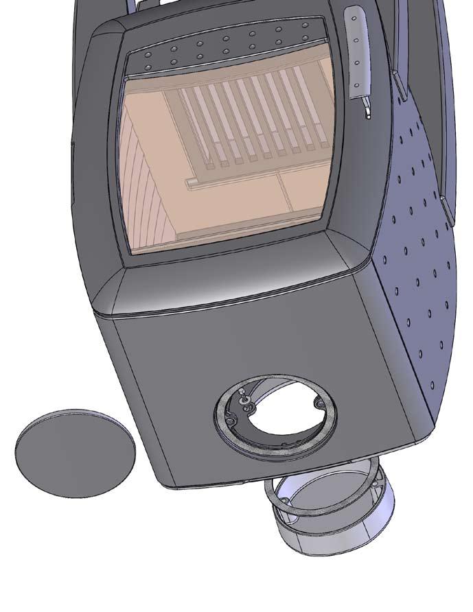


33 FIG 4.1 T FIG 4.2 T FIG 4.3 T FIG 4.4 T 33


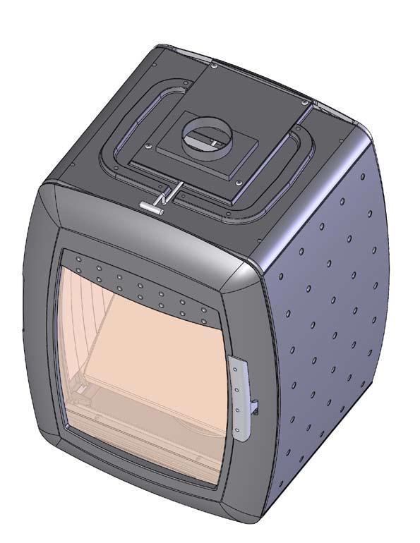

34 FIG 5 A FIG 6 FIG 5 B FIG 7 FIG 5 C 34
www.vardeovne.dk CASA Brukerveiledning Product no: 49 66 00, 49 66 01 Sintef no: 110-0251 Nordpeis : 29.08.08
 www.vardeovne.dk NO Brukerveiledning CASA Product no: 49 66 00, 49 66 01 Sintef no: 110-0251 Nordpeis : 29.08.08 INNHOLD 1. Før du installerer peisovnen 2 Krav til gulvplate 2 2. Teknisk informasjon 3
Roma Garden Art.no: FP-ROMGR-100 Last updated: 12.07.13
 NOMonteringsanvisning 2 GB Assembly instructions 3 Roma Garden Art.no: FP-ROMGR-100 Last updated: 12.07.13 Roma Garden Vekt Krav til gulvplate 352 kg 670 mm Ta kontakt med en faghandler om du trenger tips
Smarty. NO Brukerveiledning 2 GB User manual 10 DK Brugervejledning 15 SE Installations- och bruksanvisning 21 FI Käyttöohje 27
 Smarty NO Brukerveiledning 2 GB User manual 10 DK Brugervejledning 15 SE Installations- och bruksanvisning 21 FI Käyttöohje 27 Product no: SN-00005-xxx Sintef no: 110-0302 RRF no: 40 09 1921 Last updated:
Monterings- og Bruksanvisning N-36V
 Monterings- og Bruksanvisning N-36V Peisinnsats fra Nordpeis AS Gratulerer med din nye peisinnsats fra Nordpeis. Innsatsen er testet og dokumentert av Norges Branntekniske Laboratorium AS (SINTEF) i henhold
NO Monteringsanvisning s 2 GB Installation manual s 9. Casa
 NO Monteringsanvisning s 2 GB Installation manual s 9 Casa Product no: 49 66 00, 49 66 01 17.06.2008 INNHOLD 1. Før du installerer peisovnen 2 Krav til gulvplate 2 2. Teknisk informasjon 3 3. Brannmur
Orion NO GB. Brukerveiledning 2 User manual 9
 Orion NO GB Brukerveiledning 2 User manual 9 Produkt nr: SN-00000-000 Sintef nr: 045-047 Sist oppdatert: 23.11..2009 INNHOLD 1. Før du installerer nytt ildsted 2 Installasjon og kontroll før bruk 2 Pipetrekk
REMOVE CONTENTS FROM BOX. VERIFY ALL PARTS ARE PRESENT READ INSTRUCTIONS CAREFULLY BEFORE STARTING INSTALLATION
 2011-2014 FORD EXPLORER PARTS LIST Qty Part Description Qty Part Description 1 Bull Bar 2 12mm x 35mm Bolt Plates 1 Passenger/Right Mounting Bracket 2 12mm Nut Plate 1 Driver/Left Mounting Bracket 2 12mm
Trio. Monteringsanvisning 2 Installation manual 10 Manuel d installation 16 Manuale d`installazione 22 GB FR IT
 Trio NO GB FR IT Monteringsanvisning 2 Installation manual 10 Manuel d installation 16 Manuale d`installazione 22 Product no: SN-00006-xxx Sintef no: 110-0301 Last updated: 20.10.08 INNHOLD 1. Før du installerer
Bergen. NO Brukerveiledning 2 GB User manual 9. Product no: SA-BERG0-000 RRF no: 40 10 2244 Last updated: 27.05.10
 Bergen NO Brukerveiledning 2 GB User manual 9 Product no: SA-BERG0-000 RRF no: 40 10 2244 Last updated: 27.05.10 INNHOLD 1. Før du installerer nytt ildsted 2 Installasjon og kontroll før bruk 2 Pipetrekk
Modell ILD 9-AP, ILD 10-AP og ILD 11-AP
 ILD 9-AP, ILD 10-AP og ILD 11-AP: EN 13240 NS 3058 Bruksanvisning nr. 10052419-P00 30.10.2018 Modell ILD 9-AP, ILD 10-AP og ILD 11-AP INNHOLD Side Takk for tilliten.. 3 Teknisk datablad..... 3 Før montering.....
N-23G. NO Brukermanual 2 EN User manual 10
 N-23G NO Brukermanual 2 EN User manual 10 Product no: IN-00N23-xxx Sintef no: 110-0264 Last updated: 17.09.2008 INNHOLD 1. Før du installerer innsatsen 3 Installasjon og kontroll før bruk 3 Tilførsel av
The regulation requires that everyone at NTNU shall have fire drills and fire prevention courses.
 1 The law The regulation requires that everyone at NTNU shall have fire drills and fire prevention courses. 2. 3 Make your self familiar with: Evacuation routes Manual fire alarms Location of fire extinguishers
Fyringsveiledning 10.01.2012
 10.01.2012 Fyringsveiledning Innhold 1. Å fyre riktig er viktig 3 Hva er kvalitetsved 3 Riktig lagring av ved 3 Hvordan måle fuktinnholdet i lagret ved 3 Hvilken ved skal man fyre med 3 Man skal IKKE fyre
Midnight BBQ Light USER MANUAL
 Midnight BBQ Light USER MANUAL Instructions The Midnight BBQ Light uses 4 x LR44 / AG13 batteries, included in the package. Unscrew the bottom cover and insert the included batteries and align the battery
Vega. NO Brukerveiledning 2 GB User manual 9. Produkt nr: SN-00001-000 Sintef nr: 045-055 Sist oppdatert: 02.04.12
 Vega NO Brukerveiledning 2 GB User manual 9 Produkt nr: SN-00001-000 Sintef nr: 045-055 Sist oppdatert: 02.04.12 INNHOLD 1. Før du installerer nytt ildsted 2 Installasjon og kontroll før bruk 2 Skorsteinstrekk
MONTERINGSANVISNING. Ulefos antikkovn. Takk for at du har valgt Ulefos etasjeovn
 MONTERINGSANVISNING Ulefos antikkovn Takk for at du har valgt Ulefos etasjeovn Bruk og montering Det er et eksklusivt og tradisjonsrikt produkt du har valgt til hjemmet ditt. Vår etasjeovn er produsert
INSTALLATION GUIDE FTR Cargo Rack Regular Ford Transit 130" Wheelbase ( Aluminum )
") INSTALLATION GUIDE 1505-FTR Cargo Rack Regular Ford Transit 130" Wheelbase ( Aluminum ) QUICK START GUIDE Phase 1 - Assembly q 1.1 Setup... q 1.2 Cargo Rack Assembly... 3-4 5-6 Phase 2 - Installation q
INSTALLATION GUIDE 1505-FTR Cargo Rack Regular Ford Transit 130" Wheelbase ( Aluminum ) QUICK START GUIDE Phase 1 - Assembly q 1.1 Setup... q 1.2 Cargo Rack Assembly... 3-4 5-6 Phase 2 - Installation q
N-36A. NO Brukerveiledning 2 GB User manual 9
 N-36A NO Brukerveiledning 2 GB User manual 9 Product no: IN-0N36A-000 Sintef no: RRF no: Last updated: 05.07.2013 INNHOLD 1. Før du installerer innsatsen 2 Installasjon og kontroll før bruk 2 Skorsteinstrekk
Justeringsanvisninger finnes på de to siste sidene.
 d Montering av popup spredere Justeringsanvisninger finnes på de to siste sidene. Link til monteringsfilm på youtube: http://youtu.be/bjamctz_kx4 Hver spreder har montert på en "svinkobling", det vil si
Orion NO GB. Brukerveiledning 2 User manual 9
 Orion NO GB Brukerveiledning 2 User manual 9 Produkt nr: SN-00000-000 Sintef nr: 045-047 Sist oppdatert: 08.04.2012 INNHOLD 1. Før du installerer nytt ildsted 2 Installasjon og kontroll før bruk 2 Skorsteinstrekk
Windlass Control Panel
 SIDE-POWER 86-08955 Windlass Control Panel v1.0.2 Windlass Systems Installasjon manual SLEIPNER MOTOR AS P.O. Box 519 N-1612 Fredrikstad Norway Tel: +47 69 30 00 60 Fax: +47 69 30 00 70 w w w. s i d e
Product no: IN-00N36-xxx Sintef no: RRF no: Last updated:
 N-36V NO Brukerveiledning 2 GB User manual 10 DK Brugervejledning 16 SE Installations- och bruksanvisning 22 FI Käyttöohje 28 FR Manuel d installation 34 IT Manuale d installazione 41 DE Montageanleitung
X-25F. NO Brukerveiledning 2 GB User manual 9. Product no: IN-0X25F-100 Sintef no: 10204435B RRF no: 40 13 3328 Last updated: 071013
 X-25F NO Brukerveiledning 2 GB User manual 9 Product no: IN-0X25F-100 Sintef no: 10204435B RRF no: 40 13 3328 Last updated: 071013 Innhold 1. Før du installerer nytt ildsted 2 Installasjon og kontroll
Modell ILD 7-AP og ILD 8-AP
 ILD 7-AP & ILD 8-AP: EN 13240 - NS 3058 - AEA Bruksanvisning nr. 10052418-P00 30.10.2018 Modell ILD 7-AP og ILD 8-AP 2 INNHOLD Side Takk for tilliten.. 4 Teknisk datablad..... 4 Før montering..... 4 Emballasje......
5 enkle trinn. - sånn tenner du opp
 5 enkle trinn - sånn tenner du opp Utilstrekkelig skorsteinstrekk gir vanligvis problemer Opptenningsproblemer Røykutslag i rommet Sot på glass i ildstedet Bålet slukker Soting og røyklukt fra ildstedet
Q-34AL. NO Brukerveiledning 2 GB User manual 9
 Q-34AL NO Brukerveiledning 2 GB User manual 9 Product no: 46378806/ 46378795 Sintef no: RRF no: Last updated: 14.10.2013 INNHOLD 1. Før du installerer innsatsen 2 Installasjon og kontroll før bruk 2 Skorsteinstrekk
S-26R(NI-26) NO Brukerveiledning 2 GB User manual 9 SE Installation- och bruksanvisning 15
 NO Brukerveiledning 2 GB User manual 9 SE Installation- och bruksanvisning 15") S-26R(NI-26) NO Brukerveiledning 2 GB User manual 9 SE Installation- och bruksanvisning 15 Product no: IN-0NI26-020 RRF no: 29 09 2201 Last updated: 09.12.2014 INNHOLD 1. Før du installerer nytt ildsted
S-26R(NI-26) NO Brukerveiledning 2 GB User manual 9 SE Installation- och bruksanvisning 15 Product no: IN-0NI26-020 RRF no: 29 09 2201 Last updated: 09.12.2014 INNHOLD 1. Før du installerer nytt ildsted
5 enkle trinn - sånn tenner du opp
 www.exodraft.no 5 enkle trinn - sånn tenner du opp Den enkle løsningen mot dårlig skorsteinstrekk Ved å installere en exodraft-røyksuger skapes optimal trekk i skorsteinen uansett vær, samt også: Bedre
INSTALLATION GUIDE FTR Cargo Rack Regular Ford Transit 130" Wheelbase ( Aluminum )
") INSTALLATION GUIDE 1505-FTR Cargo Rack Regular Ford Transit 130" Wheelbase ( Aluminum ) QUICK START GUIDE Phase 1 - Assembly q 1.1 Setup... q 1.2 Cargo Rack Assembly... 3-4 5-6 Phase 2 - Installation q
INSTALLATION GUIDE 1505-FTR Cargo Rack Regular Ford Transit 130" Wheelbase ( Aluminum ) QUICK START GUIDE Phase 1 - Assembly q 1.1 Setup... q 1.2 Cargo Rack Assembly... 3-4 5-6 Phase 2 - Installation q
Q-23FL. NO Brukerveiledning 2 GB User manual 9
 Q-23FL NO Brukerveiledning 2 GB User manual 9 Product no: 46378780 Sintef no: RRF no: Last updated: 14.10.2013 INNHOLD 1. Før du installerer innsatsen 2 Installasjon og kontroll før bruk 2 Skorsteinstrekk
Installasjonsveiledning I 40/ /
 Installasjonsveiledning NO I 40/55 01.06.2019 / 97-9693 www.hwam.com 2 INNHOLDSFORTEGNELSE TEKNISKE DATA...4 Generelt...4 Sikkerhet...4 Krav til rommet...4 Tekniske mål og data...4 Typeskilt og serienummer...5
Perpetuum (im)mobile
mobile") Perpetuum (im)mobile Sett hjulet i bevegelse og se hva som skjer! Hva tror du er hensikten med armene som slår ut når hjulet snurrer mot høyre? Hva tror du ordet Perpetuum mobile betyr? Modell 170, Rev.
Perpetuum (im)mobile Sett hjulet i bevegelse og se hva som skjer! Hva tror du er hensikten med armene som slår ut når hjulet snurrer mot høyre? Hva tror du ordet Perpetuum mobile betyr? Modell 170, Rev.
X-20 F. NO Brukerveiledning 2 GB User manual 9. Product no: IN-0X20F-010 Teknologisk no: 300-ELAB-2025-EN II Last updated:
 X-20 F NO Brukerveiledning 2 GB User manual 9 Product no: IN-0X20F-010 Teknologisk no: 300-ELAB-2025-EN II Last updated: 130314 GB 1 Innhold 1. Før du installerer nytt ildsted 2 Skorsteinstrekk 2 Tilførsel
X-20 F. NO Brukerveiledning 2. GB User manual 9. Product no: IN-0X20F-010 Teknologisk no: 300-ELAB-2025-EN II Last updated: 130314
 X-20 F NO Brukerveiledning 2 7 8 9 10 11 12 GB User manual 9 A B C D E F G DRAWN NAME P.Żabiński SIGNATURE DATE 2012-07-18 NAME: IN-0X20F-010 X20F - Insert A2 CHK'D D.Krzyżaniak 2013-11-29 SCALE:1:5 7
Glasgow. NO Monterings- og bruksanvisning 2 GB Installation- and user manual 9
 Glasgow NO Monterings- og bruksanvisning 2 GB Installation- and user manual 9 Product no: SN-GLASG-010 Test report no: RRF: 40 16 4328 Last updated: 16.08.2016 INNHOLD 1. Før du installerer nytt ildsted
N-23G. NO Brukerveiledning 2 GB User manual 10 DK Brugervejledning 17 SE Installations- och bruksanvisning 23 FI Käyttöohje 29
 N-23G NO Brukerveiledning 2 GB User manual 10 DK Brugervejledning 17 SE Installations- och bruksanvisning 23 FI Käyttöohje 29 Product no: IN-00N23-xxx Sintef no: 110-0264 RRF no: 29 09 1915 Last updated:
Start Here USB *CC * *CC * USB USB
 1 USB Start Here USB 11 USB WARNING: To ensure that the software is installed correctly, do not connect the USB cable until step 11. 11 USB 2 a. b. Lower both the paper tray and the print cartridge door.
Glasgow. NO Monterings- og bruksanvisning 2 GB Installation- and user manual 9
 Glasgow NO Monterings- og bruksanvisning 2 GB Installation- and user manual 9 Product no: SN-GLASG-010 Test report no: RRF: 40 16 4328, NS 16 4328 Last updated: 21.02.2019 VIKTIGE SIKKERHETSREGLER: 1.
KAMPANJE APK : APK-5: Skifte pakninger mellom turbo og CCDPF
 KAMPANJE APK-5 20150722: APK-5: Skifte pakninger mellom turbo og CCDPF Berørte modeller for APK-5: Vitara APK416D, totalt 66 biler. Liste med chassisnummer legges ikke ved, bruk Forhandlerweb til å sjekke
Q-34AL. NO Brukerveiledning 2 GB User manual 9
 Q-34AL NO Brukerveiledning 2 GB User manual 9 Product no: 22-Q34AL-00L / 22-Q34AL-00P RRF no: 29 13 3454 Last updated: 14.03.2014 INNHOLD 1. Før du installerer innsatsen 2 Installasjon og kontroll før
Glasgow. NO Monterings- og bruksanvisning 2 GB Installation- and user manual 9
 Glasgow NO Monterings- og bruksanvisning 2 GB Installation- and user manual 9 Product no: SN-GLASG-010 Test report no: RRF: 40 16 4328, NS 16 4328 Last updated: 06.10.2017 INNHOLD 1. Før du installerer
X-20 F. NO Brukerveiledning 2. GB User manual 9 SE Bruksanvisning 15 FI Käyttöohje 21
 X-20 F NO Brukerveiledning 2 7 8 9 10 11 12 GB User manual 9 SE Bruksanvisning 15 FI Käyttöohje 21 A B C D E F G DRAWN NAME P.Żabiński SIGNATURE DATE 2012-07-18 NAME: IN-0X20F-010 X20F - Insert A2 CHK'D
Q-23FL. NO Brukerveiledning 2 GB User manual 9
 Q-23FL NO Brukerveiledning 2 GB User manual 9 Product no: 22-Q23FL-000 RRF no: 29 13 3453 Last updated: 10.07.2014 INNHOLD 1. Før du installerer innsatsen 2 Installasjon og kontroll før bruk 2 Skorsteinstrekk
Monteringsanvisning Installation manual Taksokkel for LHH og CareLite Ceiling mount for LHH and CareLite
 Monteringsanvisning Installation manual Taksokkel for LHH og CareLite Ceiling mount for LHH and CareLite Art.nr. 05-900-573-00. Page 1 of 9 Norsk Monteringsanvisning taksokkel Denne monteringsmanualen
Fitting instruction. devi-pipeheat / devi-flexheat Assembly between cold tail and selflimiting. Montering av tilledning på selvbegrensende varmekabel
 GB/NO Fitting instruction devi-pipeheat / devi-flexheat Assembly between cold tail and selflimiting heating cable Item no. 19806415 Montering av tilledning på selvbegrensende varmekabel Art. nr. 19806415
Opus Ignis. Brukerhåndbok EN 13240 NS 3058. Opus Ignis.indd 1 02.07.13 12.03
 EN 13240 NS 3058 Brukerhåndbok Opus.indd 1 02.07.13 12.03 Innhold 1. Gratulerer med ny ovn... 3 1.1 Første gangs bruk... 3 1.2 Påfylling... 3 2. Vedlikehold... 3 3. Montering... 3 4. Data... 5 5. Tilbehør...
N-20 T. NO Brukerveiledning 2 GB User manual 9 SE Bruksanvisning 16 FI Käyttöohje 23
 N-20 T NO Brukerveiledning 2 GB User manual 9 SE Bruksanvisning 16 FI Käyttöohje 23 Product no: IN-0N20T-010 Test report No: RRF: 29 15 3996 Last updated: 27.10.2015 Innhold 1. Før du installerer nytt
N-20 A. NO Brukerveiledning 2 GB User manual 10 SE Bruksanvisning 17 FI Käyttöohje 24
 N-20 A NO Brukerveiledning 2 GB User manual 10 SE Bruksanvisning 17 FI Käyttöohje 24 Product no: IN-0N20A-X11 / IN-0N20A-X14 Test report No: SPFR 20012-33B Last updated: 11.12.2018 VIKTIGE SIKKERHETSREGLER:
N-20 A. NO Brukerveiledning 2 GB User manual 10 SE Bruksanvisning 17 FI Käyttöohje 24
 N-20 A NO Brukerveiledning 2 GB User manual 10 SE Bruksanvisning 17 FI Käyttöohje 24 Product no: IN-0N20A-X11 / IN-0N20A-X14 Test report No: SPFR 20012-33B Last updated: 14.01.2019 VIKTIGE SIKKERHETSREGLER:
N-20 U. NO Brukerveiledning 2 GB User manual 10 SE Bruksanvisning 17 FI Käyttöohje 24
 N-20 U NO Brukerveiledning 2 GB User manual 10 SE Bruksanvisning 17 FI Käyttöohje 24 Product no: IN-0N20U-011 / IN-0N20U-014 / IN-0N20U-017 Test report No: SPFR 20012-20B2 Last updated: 18.12.2018 VIKTIGE
N-20 U. NO Brukerveiledning 2 GB User manual 10 SE Bruksanvisning 17 FI Käyttöohje 24
 N-20 U NO Brukerveiledning 2 GB User manual 10 SE Bruksanvisning 17 FI Käyttöohje 24 Product no: IN-0N20U-011 / IN-0N20U-014 / IN-0N20U-017 Test report No: SPFR 20012-20B2 Last updated: 15.01.2019 VIKTIGE
N-20F. NO Brukerveiledning 2 GB User manual 10 DK Brugervejledning 17 SE Installations- och bruksanvisning 24 FI Käyttöohje 31
 N-20F NO Brukerveiledning 2 GB User manual 10 DK Brugervejledning 17 SE Installations- och bruksanvisning 24 FI Käyttöohje 31 Product no: IN-00N20-100, IA-00N20-101, IA-00N20-102, IA-00N20-103, IA-00N20-104,
Q-34AL. NO Brukerveiledning 2 GB User manual 9
 Q-34AL NO Brukerveiledning 2 GB User manual 9 Product no: 46378806/ 46378795 Sintef no: RRF no: Last updated: 10.12.2013 INNHOLD 1. Før du installerer innsatsen 2 Installasjon og kontroll før bruk 2 Skorsteinstrekk
Exercise 1: Phase Splitter DC Operation
 Exercise 1: DC Operation When you have completed this exercise, you will be able to measure dc operating voltages and currents by using a typical transistor phase splitter circuit. You will verify your
N-20 U. NO Brukerveiledning 2 GB User manual 10 SE Bruksanvisning 17 FI Käyttöohje 24
 N-20 U NO Brukerveiledning 2 GB User manual 10 SE Bruksanvisning 17 FI Käyttöohje 24 Product no: IN-0N20U-011 / IN-0N20U-014 / IN-0N20U-017 Test report No: SPFR 20012-20B2 Last updated: 26.03.2019 VIKTIGE
Q-34AL. NO Brukerveiledning 2 GB User manual 9
 Q-34AL NO Brukerveiledning 2 GB User manual 9 Product no: 46378806/ 46378795 Sintef no: RRF no: Last updated: 27.09.2013 INNHOLD 1. Før du installerer innsatsen 2 Installasjon og kontroll før bruk 2 Skorsteinstrekk
Unit Relational Algebra 1 1. Relational Algebra 1. Unit 3.3
 Relational Algebra 1 Unit 3.3 Unit 3.3 - Relational Algebra 1 1 Relational Algebra Relational Algebra is : the formal description of how a relational database operates the mathematics which underpin SQL
N-20F. NO Brukerveiledning 2 GB User manual 10 DK Brugervejledning 17 SE Installations- och bruksanvisning 24 FI Käyttöohje 31
 N-20F NO Brukerveiledning 2 GB User manual 10 DK Brugervejledning 17 SE Installations- och bruksanvisning 24 FI Käyttöohje 31 Product no: IN-00N20-100, IA-00N20-106, IA-0N20D-011, IA-0N20D-014 Test no:
S-31A. NO Brukerveiledning 2 GB User manual 10 SE Installationsanvisning 17 FI Asennusohje 24
 S-31A NO Brukerveiledning 2 GB User manual 10 SE Installationsanvisning 17 FI Asennusohje 24 Product no: IN-0S31A-010 Test report No: SINTEF 102044.24; RRF - 29 16 4413 Last updated: 02.05.2017 VIKTIGE
NI-25. NO Brukerveiledning 2 GB User manual 10 DK Brugervejledning 16 SE Installations- och bruksanvisning 22 FI Käyttöohje 28
 NI-25 NO Brukerveiledning 2 GB User manual 10 DK Brugervejledning 16 SE Installations- och bruksanvisning 22 FI Käyttöohje 28 Product no: IN-00025-xxx Sintef no: 110-0213 RRF no: 29 09 1916 Last updated:
N-20F. NO Brukerveiledning 2 GB User manual 10 DK Brugervejledning 17 SE Installations- och bruksanvisning 24 FI Käyttöohje 31
 N-20F NO Brukerveiledning 2 GB User manual 10 DK Brugervejledning 17 SE Installations- och bruksanvisning 24 FI Käyttöohje 31 Product no: IN-00N20-100, IA-00N20-101, IA-00N20-102, IA-00N20-103, IA-00N20-104,
Endelig ikke-røyker for Kvinner! (Norwegian Edition)
") Endelig ikke-røyker for Kvinner! (Norwegian Edition) Allen Carr Click here if your download doesn"t start automatically Endelig ikke-røyker for Kvinner! (Norwegian Edition) Allen Carr Endelig ikke-røyker
Endelig ikke-røyker for Kvinner! (Norwegian Edition) Allen Carr Click here if your download doesn"t start automatically Endelig ikke-røyker for Kvinner! (Norwegian Edition) Allen Carr Endelig ikke-røyker
NI-25. NO Brukerveiledning 2 GB User manual 10 DK Brugervejledning 17 SE Installations- och bruksanvisning 24 FI Käyttöohje 31
 NI-25 NO Brukerveiledning 2 GB User manual 10 DK Brugervejledning 17 SE Installations- och bruksanvisning 24 FI Käyttöohje 31 Product no: IN-00025-xxx Sintef no: 102 041.42B RRF no: 29 09 1916 Last updated:
IMPORTANT! HOLD ON THIS DOCUMENT FOR LATER REFERENCE! READ CAREFULLY! VIKTIG! BEHOLD DETTE DOKUMENTET FOR FREMTIDIG BRUK! LES NØYE IGJENNOM!
 GB IMPORTANT! HOLD ON THIS DOCUMENT FOR LATER REFERENCE! READ CAREFULLY! NOR VIKTIG! BEHOLD DETTE DOKUMENTET FOR FREMTIDIG BRUK! LES NØYE IGJENNOM! Produktmål, materiale: 135x77x72 cm Furu Proper use This
NO GB. Monteringsanvisning 2 Installation manual 10. Ronda 160 Soapstone
 NO GB Monteringsanvisning 2 Installation manual 10 Ronda 160 Soapstone Art.no: CC-RON04-1X0 Last updated: 11.12.2013 Innhold 1. Generelt om elementpeiser 1. Generelt om elementpeiser 2 Vekt 2 Brannmur
MCP-16RC, luftrenertårn
 Kompakt filterkassett med pulsrengjøring MCP-16RC luftrensertårn er en kompakt filterkassett for desentralisert inneluftrengjøring der luftgjenoppretting er mulig. Den kompakte filterenheten leveres med
Ronda med innsats / with insert
 NO Brukerveiledning 2 GB User manual 9 DK Brugervejledning 15 FR Manuel d installation 21 DE Montageanleitung 28 SE Monteringsanvisning 39 Ronda med innsats / with insert Art.no: CC-RIO00-100, CC-RIO01-100
Q-23FL. NO Brukerveiledning 2 GB User manual 9
 Q-23FL NO Brukerveiledning 2 GB User manual 9 Product no: 22-Q23FL-000 RRF no: 29 13 3453 Last updated: 24.03.2014 INNHOLD 1. Før du installerer innsatsen 2 Installasjon og kontroll før bruk 2 Skorsteinstrekk
Slope-Intercept Formula
 LESSON 7 Slope Intercept Formula LESSON 7 Slope-Intercept Formula Here are two new words that describe lines slope and intercept. The slope is given by m (a mountain has slope and starts with m), and intercept
N-20 T. NO Brukerveiledning 2 GB User manual 10 SE Bruksanvisning 17 FI Käyttöohje 24
 N-20 T NO Brukerveiledning 2 GB User manual 10 SE Bruksanvisning 17 FI Käyttöohje 24 Product no: IN-0N20T-010 Test report No: RRF: 29 15 3996 Last updated: 14.12.2018 VIKTIGE SIKKERHETSREGLER: 1. Følg
Replacing the tube and/or tyre of a drive wheel, indoor/outdoor
 ASSEMBLY INSTRUCTION Replacing the tube and/or tyre of a drive wheel, indoor/outdoor EN NO 9010182A 5.2.7 9010182 Replacing the tube and/or tyre of a drive wheel, indoor/outdoor Preparation Be sure that
Product Facts. Product code example
 ESAM Smoke control damper for multi Rectangular smoke control damper ESAM is specifically designed for use in multi fire compartment applications as a closing or as an opening damper for smoke extract
bondura dual 36 Ø50mm - Ø200mm assembly & inspection manual art rev A
 bondura dual 36 Ø50mm - Ø200mm assembly & inspection manual art. 103803 rev. 27.04.2016 A TABLE OF CONTENT / INNHOLD 1/ assembly montering 2/ technical specifications/torque tekniske data/tiltrekkingsmoment
GYRO MED SYKKELHJUL. Forsøk å tippe og vri på hjulet. Hva kjenner du? Hvorfor oppfører hjulet seg slik, og hva er egentlig en gyro?
 GYRO MED SYKKELHJUL Hold i håndtaket på hjulet. Sett fart på hjulet og hold det opp. Det er lettest om du sjølv holder i håndtakene og får en venn til å snurre hjulet rundt. Forsøk å tippe og vri på hjulet.
Q-34AL. NO Brukerveiledning 2 GB User manual 9
 Q-34AL NO Brukerveiledning 2 GB User manual 9 Product no: 22-Q34AL-00L / 22-Q34AL-00P RRF no: 29 13 3454 Last updated: 07.04.2014 INNHOLD 1. Før du installerer innsatsen 2 Installasjon og kontroll før
X-25F. NO Brukerveiledning 2 GB User manual 9 SE Installationsanvisning 15
 X-25F NO Brukerveiledning 2 GB User manual 9 SE Installationsanvisning 15 Product no: IN-0X25F-100 Sintef no: 10204435B RRF no: 40 13 3328 Last updated: 071013 Innhold 1. Før du installerer nytt ildsted
STILLAS - STANDARD FORSLAG FRA SEF TIL NY STILLAS - STANDARD
 FORSLAG FRA SEF TIL NY STILLAS - STANDARD 1 Bakgrunnen for dette initiativet fra SEF, er ønsket om å gjøre arbeid i høyden tryggere / sikrere. Både for stillasmontører og brukere av stillaser. 2 Reviderte
NO Brukerveiledning 2 GB User manual 10 SE Monteringsanvisning 17. Art.no: FP-HAV00-000 02.03.2012 RRF 40 12 2937. Havanna med innsats / with insert
 NO Brukerveiledning 2 GB User manual 10 SE Monteringsanvisning 17 Art.no: FP-HAV00-000 02.03.2012 RRF 40 12 2937 Havanna med innsats / with insert Innhold 1. Generelt om elementpeiser 2 Vekt 2 Tilkobling
Product no: IN-00N22-xxx Sintef no: RRF no: Last updated:
 NI-22 NO Brukerveiledning 2 GB User manual 10 DK Brugervejledning 16 FR Manuel d installation 22 DE Montageanleitung 29 SE Installations- och bruksanvisning 39 Product no: IN-00N22-xxx Sintef no: 041-169
Norsk (English below): Guide til anbefalt måte å printe gjennom plotter (Akropolis)
: Guide til anbefalt måte å printe gjennom plotter (Akropolis)") Norsk (English below): Guide til anbefalt måte å printe gjennom plotter (Akropolis) 1. Gå til print i dokumentet deres (Det anbefales å bruke InDesign til forberedning for print) 2. Velg deretter print
Norsk (English below): Guide til anbefalt måte å printe gjennom plotter (Akropolis) 1. Gå til print i dokumentet deres (Det anbefales å bruke InDesign til forberedning for print) 2. Velg deretter print
X-25F. NO Brukerveiledning 2 GB User manual 9 SE Installationsanvisning 15
 X-25F NO Brukerveiledning 2 GB User manual 9 SE Installationsanvisning 15 Product no: IN-0X25F-100 Sintef no: 10204435B RRF no: 40 13 3328 Last updated: 16.10.2017 Innhold 1. Før du installerer nytt ildsted
5 E Lesson: Solving Monohybrid Punnett Squares with Coding
 5 E Lesson: Solving Monohybrid Punnett Squares with Coding Genetics Fill in the Brown colour Blank Options Hair texture A field of biology that studies heredity, or the passing of traits from parents to
Montering av Lian Skyvedør Installation of Lian Sliding Door
 Montering av Lian Skyvedør Installation of Lian Sliding Door Les dette før du starter monteringen! Read these instructions carefully before installation. Sjekk nøye at produktet stemmer med bestilling
NO GB. Monteringsanvisning 2 Installation manual 10. Ronda 160 Soapstone
 NO GB Monteringsanvisning 2 Installation manual 10 Ronda 160 Soapstone Art.no: CC-RON04-1X0 Last updated: 27.08.2013 Innhold 1. Generelt om elementpeiser 1. Generelt om elementpeiser 2 Vekt 2 Brannmur
NO GB. Monteringsanvisning 2 Installation manual 10. Ronda 160 Soapstone
 NO GB Monteringsanvisning 2 Installation manual 10 Ronda 160 Soapstone Art.no: CC-RON04-1X0 Last updated: 11.12.2013 Innhold 1. Generelt om elementpeiser 1. Generelt om elementpeiser 2 Vekt 2 Brannmur
TECHNOLOGIE POUR CHAUDIERES DE BRUNNER. Kamin-Kessel Eck 57/67/44 Porte relevable (easy-lift) État: made in germany
 État: made in germany") TCHNOLOGI POUR CHAUDIRS D BRUNNR KaminKessel ck 57/67/44 Porte relevable (easylift) État: 01.12.2016 made in germany KaminKessel ck 57/67/44 Porte relevable (easylift) S securité départ 1/2" fil.ext. securité
TCHNOLOGI POUR CHAUDIRS D BRUNNR KaminKessel ck 57/67/44 Porte relevable (easylift) État: 01.12.2016 made in germany KaminKessel ck 57/67/44 Porte relevable (easylift) S securité départ 1/2" fil.ext. securité
NI-25. NO Brukerveiledning 2 GB User manual 10 DK Brugervejledning 16 SE Installations- och bruksanvisning 22 FI Käyttöohje 28
 NI-25 NO Brukerveiledning 2 GB User manual 10 DK Brugervejledning 16 SE Installations- och bruksanvisning 22 FI Käyttöohje 28 Product no: IN-00025-xxx Sintef no: 110-0213 RRF no: 29 09 1916 Last updated:
KROPPEN LEDER STRØM. Sett en finger på hvert av kontaktpunktene på modellen. Da får du et lydsignal.
 KROPPEN LEDER STRØM Sett en finger på hvert av kontaktpunktene på modellen. Da får du et lydsignal. Hva forteller dette signalet? Gå flere sammen. Ta hverandre i hendene, og la de to ytterste personene
SN-QUADR-510, SN-QUADR-520,SN-QUADR-530
 Quadro Basic NO Monterings- og bruksanvisning 2 GB Installation- and user manual 9 SE Installations- och bruksanvisning 15 FI Asennus- ja käyttöohje 21 DE Installations- und Benutzerhandbuch 27 FR Manuel
N-20 U. NO Brukerveiledning 2 GB User manual 9 SE Bruksanvisning 16 FI Käyttöohje 22
 N-20 U NO Brukerveiledning 2 GB User manual 9 SE Bruksanvisning 16 FI Käyttöohje 22 Product no: IN-0N20U-010 / IN-0N20U-014 Test report No: SPFR 20012-20B2 Last updated: 16.10.2015 Innhold 1. Før du installerer
N-20 A. NO Brukerveiledning 2 GB User manual 9 SE Bruksanvisning 16 FI Käyttöohje 22
 N-20 A NO Brukerveiledning 2 GB User manual 9 SE Bruksanvisning 16 FI Käyttöohje 22 Product no: IN-0N20U-010 / IN-0N20U-014 Test report No: SPFR 20012-33B Last updated: 21.04.2016 Innhold 1. Før du installerer
BRUKSANVISNING STØVSUGER D 775
 BRUKSANVISNING STØVSUGER D 775 1 Støvindikator Støvsugeren kjenner selv av når sugeeffekten blir dårlig på grunn av full eller gjentettet støvbeholder. Når støvindikatoren lyser bør støvbeholderen byttes.
Elektronisk termostat med spareprogram. Lysende LCD display øverst på ovnen for enkel betjening.
 Elektronisk termostat med spareprogram. Lysende LCD display øverst på ovnen for enkel betjening. 27.5 LCD Electronic thermostat with program setting. Bright LCD display placed at the top of the heater
N-36V. NO Brukerveiledning 2 GB User manual 10 DK Brugervejledning 16 SE Installations- och bruksanvisning 22 FI Käyttöohje 28
 N-36V NO Brukerveiledning 2 GB User manual 10 DK Brugervejledning 16 SE Installations- och bruksanvisning 22 FI Käyttöohje 28 Product no: IN-00N36-xxx Sintef no: 110-0214 RRF no: 29 09 1918 Last updated:
Manhattan II, Manhattan High II. !kg. NO Monteringsanvisning 2 GB Installation manual 4
 NO Monteringsanvisning 2 GB Installation manual 4!kg Manhattan II, Manhattan High II Art.no: FP-MAN02-101, FP-MAN02-201 Last updated: 16.09.2014 Test Report No: 40 13 03327 Generelt om element peiser Vekt
Chicago II/ Chicago II High
 NO Monteringsanvisning 2 GB Installation manual 4 Chicago II/ Chicago II High!kg Art.no: FP-CH002-100 Last updated:101213 Generelt om elementpeiser Vekt Huseier må forsikre seg om at gulvet tåler belastningen
Trigonometric Substitution
 Trigonometric Substitution Alvin Lin Calculus II: August 06 - December 06 Trigonometric Substitution sin 4 (x) cos (x) dx When you have a product of sin and cos of different powers, you have three different
Brukerveiledning. !kg. Berlin. Art.no: FP-BER00-X00 Test report no: XXX XXXX-XXX Last updated:
 NO Brukerveiledning 2 Berlin!kg Art.no: FP-BER00-X00 Test report no: XXX XXXX-XXX Last updated: 19.01.2018 VIKTIGE SIKKERHETSREGLER: 1. Følg monteringsanvisningen nøye når ildstedet tilkobles skorsteinen.
N-20F(N-20) NO Brukerveiledning 2 GB User manual 9 DK Brugervejledning 15 SE Installations- och bruksanvisning 21 FI Käyttöohje 27
 NO Brukerveiledning 2 GB User manual 9 DK Brugervejledning 15 SE Installations- och bruksanvisning 21 FI Käyttöohje 27") N-20F(N-20) NO Brukerveiledning 2 GB User manual 9 DK Brugervejledning 15 SE Installations- och bruksanvisning 21 FI Käyttöohje 27 Product no: IN-00N20-XXX Sintef no: 110-0321 Last updated 01.01.2013 INNHOLD
N-20F(N-20) NO Brukerveiledning 2 GB User manual 9 DK Brugervejledning 15 SE Installations- och bruksanvisning 21 FI Käyttöohje 27 Product no: IN-00N20-XXX Sintef no: 110-0321 Last updated 01.01.2013 INNHOLD