WiMEA. Owner`s Manual D Ø D M A N N S K N A S L Ø R Å D W I R E L E C T I S W
|
|
|
- Sigrun Stene
- 8 år siden
- Visninger:
Transkript
1 T P H WiMEA Owner`s Manual R Å D S L Ø D Ø D M A N N S K N A P W I R E L E S S K I L L I S W C T

2 Package content Introduction English 1. The team behind FELL thank you for engaging in a new and innovative way of being safe while boating. Our mission is to enable all boaters to enjoy the seas, being free. We call it Safe To Be Free When making this product we expected that our customers wanted the free and energizing feeling when spending time on the sea, either being high seas or low seas, rainy or sunny. We wanted to enhance the boating experience by creating a product, which you can forget wearing, providing absolute safety no worries, just be free and enjoy. 4. Still after several decades of using a corded solution for the engine kill switch on motorboats, no one seemed to have developed a system that enables one to be free and safe while driving a motor boat as it should be WiMEA Boat WiMEA Unit Boat Unit External Antenna External Antenna 3. Adjustable Wristband 3. Wristband 4. WiMEA MOB Unit 4. WiMEA MOB Unit 5. Connection Cable 6 5. Connection Cable x 1 x 1 x 1 x 1 x 1 Using state of the art wireless technology and highly advanced wireless microprocessors from Texas Instruments, we have developed the effortless and easy to use WiMEA by FELL of Norway. Developing and using the most advanced wireless technology available, the WiMEA8 Protocol is the most advanced wireless safety system on the maritime market. We hope you will enjoy your time spent boating just a little more with your WiMEA onboard! Your FELL-team Developed by: FELL & Eker Design 7

3 WiMEA Install Guide 24 25

4 Boat Unit Components Mounting the Boat Unit 1. Remove the Boat Unit Nut by turning it off. 2. Attach the External Antenna by turning it onto the antenna connector at the bottom of the Boat Unit. 3. Drill a hole in your helm for the Boat Unit. Use standard 52 mm hole cup drill to make the hole. NOTICE Be sure not to drill through any existing cables or equipment mounted or situated on the backside of your intended Boat Unit position! Lead the Boat Unit Cable and External Antenna into the hole and thereafter place the Boat Unit in the hole. 5. Place the gasket between the flange under the top of the Boat Unit and the surface of the helm/wall surrounding the hole. 6. When positioning the Boat Unit in the helm or other suitable place, make sure to set the direction of the Boat Unit with the battery indicator at 12 o clock and the FELL printing at six o clock. 7. Tighten the Boat Unit Nut from behind to securely attach the Boat Unit in the helm. The Boat Unit Nut is fitted by using normal hand force. 8. Attach the Boat Unit Cable and the Connection Cable by connecting the male and female 5-Pin Connectors together on the two cables. 9. Proceed to connecting the wires, see page 30 Connecting the wires. 27

5 NOTICE The Boat Unit should be mounted in the helm or as near as possible to the driver position of the boat. FAILURE TO FOLLOW THESE INSTALLATION INSTRUCTIONS COULD RESULT IN FIRE, ELECTRIC SHOCK, OR OTHER INJURY OR DAMAGE. TIP It may be easier to connect the kill switch signal wires to the Connection Cable before mounting the Boat Unit completely in your helm, depending on your helm/boat. Connect the wires for the Connection wires as described in section Connecting the wires. Then connect the Boat Unit Cable and the Connection Cable by connecting the male and female 5-pin IP67 Connectors before doing final mounting of the Boat Unit. Connect the Boat Unit Cable to the Connection Cable between bullet point 3 and 4 on page 26, Mounting the Boat Unit. NOTICE We recommend that the installation of the WiMEA in your boat is performed by skilled personnel familiar with electric wiring, or by a professional mechanic or electrician. This is to prevent any malfunction of the device related to installation

6 Connecting the Wires NOTICE Do not touch or cut any existing wires or electrically conducting components before you make sure the main voltage switch is OFF. Only set the main voltage switch to ON after you are finished cutting and connecting wires. Make sure that all wires and conductive connection points are free from corrosion before connecting any wires

7 Connecting the Power (10 32Vdc) 1. Use a test light or a voltmeter to determine the polarity of the voltage source. 2. Connect the red (+ or positive) wire to the positive voltage terminal. (If you use the fuse block on the boat, route the positive connection through the fuse, as shown on the diagram.) 3. Connect the black (- or ground) wire to the negative voltage terminal. 4. Install or check the 1 A fuse (in the in-line fuse holder, or on the fuse block of the boat. 5. Use wire hoods suitable for the wire dimension (20AWG, 0.75mm2) or connection point on the fuse block. NOTICE Use an AGC / 3AG 1 Amp replacement fuse. If it is necessary to extend the power and ground wires, use 20 AWG or thicker wire. You can wire the Power Wires directly to the main boat battery, or if your boat has an electrical system, you might be able to wire the Power Wires to an unused holder on the fuse block. If your boat has an NMEA or NMEA2000 system installed you can use this system as a power supply for the WiMEA Boat Unit, if enough power is available. Please make sure to check a relevant source for information on power availability in your NMEA system. NMEA website: WARNING The maximum WiMEA Boat Unit input voltage is 32 Vdc. Do not exceed this voltage because this can damage the WiMEA Boat Unit and void the warranty

8 Connecting the WiMEA Signal wires Before connecting the Boat Unit Signal wires, you must test which kill switch principle is used by your engine manufacturer. The engine signal wires on WiMEA Boat Unit consists of three wires. Only two of the three wires are used to connect to the existing kill switch wires in your boat. Below are instructions on how to test which of the Boat Unit signal wires to use and how to connect them to the existing wires in your boat. Overview of the Boat Unit signal wires (see picture on page 30 for overview of the signal wires): NOTICE 1. Common Grey Always used when connecting the WiMEA Boat Unit Signal wires. 2. Normally Open (NO) Blue Used when your existing system is a Normally Open kill switch system. 3. Normally Closed (NC) Orange Used when your existing system is a Normally Closed kill switch system. The engine kill switch system principle varies across different engine manufacturers, and different year of model, being Normally Open or Normally Closed principle. Some existing kill switches has three wires, you still only need to connect two as described in this manual. The principle in the existing mechanical kill switch is the same as the Boat Unit Signal wires, where the three wires makes the existing kill switch compatible with both Normally Open and Normally Closed kill switch systems The existing kill switch system in your engine is either: 1. Normally Open (NO) meaning that the kill switch opens and disconnects the conductive latch to stop the engine. 2. Normally Closed (NC) meaning that the kill switch closes and connects the conductive latch to stop the engine. The existing kill switch system has two wires, which are connected to the mechanical kill switch (the switch to attach the standard red cord), mounted in your helm, in the throttle quadrant, on your engine or other suitable place near the driving position. To connect the Boat Unit Signal wires you must first cut and strip the existing kill switch wiring as shown on the picture below: After stripping the two existing wires, proceed to test the kill switch principle, as described below. See page 39, Wiring diagram for overview of the wire connections. NOTICE The grey wire on the Connection Cable is the CMN (common wire) and is used to connect to one of the existing engine kill switch signal wires, regardless of the existing kill switch principle mm
: NOTICE 1. Common Grey Always used when connecting the WiMEA Boat Unit Signal wires. 2.")
9 Testing the kill switch principle (Normally Open / Normally Closed) Testing with multimeter You can test the kill switch principle by connecting a multimeter to both cables from the existing mechanical kill switch. Make sure the multimeter is set to measure resistance. See picture on page 37 for reference on how to measure. Infinite resistance measured: You have a Normally Open (NO) Kill Switch Use Blue wire and Grey wire on the Boat Unit to connect to the two existing kill switch wires from your engine. See wiring diagram for Normally Open on page 39. Close to 0 (zero) resistance: You have a Normally Closed (NO) Kill Switch Use Orange wire and Grey wire on the Boat Unit to connect to the two existing kill switch wires in your boat. See wiring diagram for Normally Closed on page

10 Testing with the existing wires Wiring diagram 1. Make sure the existing kill switch wires are not in contact after you have cut and stripped the two wires. 2. Make sure your throttle or gear handle is in neutral position. You are going to start the engine to check which principle is used by your engine manufacturer. 3. Turn the engine ignition switch to ON as you would normally do when starting the engine. If you have a pull cord, be sure to check if you can stop the engine by pressing a STOP BUTTON on your engine. If you do not have a STOP BUTTON on your engine: In the event that the engine starts when the existing kill switch wires are not in conductive contact, and you have pulled the pull cord to perform normal engine start, you can stop the engine by reconnecting the wires. Simply by leading them together on the stripped end of both wires, where the cable metal is conductive. WARNING PREVENT ELECTRIC SHOCK: Be sure not to touch the conducting surface on the wires as these may conduct electricity! 4. Be sure to perform normal starting procedure when testing, as described above in point Yielded result: No engine start: You have a Normally Open (NO) Kill Switch Use blue wire and grey wire on the Boat Unit to connect to the two existing kill switch wires in your boat. See wiring diagram for Normally Open on page 39. Engine start: You have a Normally Closed (NO) Kill Switch Use orange wire and grey wire on the Boat Unit Cable to connect to the two existing kill switch wires in your boat. See wiring diagram for Normally Closed on page 39. From WiMEA Boat Unit 5-pin IP67 Connector From WiMEA Boat Unit 5-pin IP67 Connector Normally open Red Black Gray Blue Orange Red Black Gray Blue Orange Fuse 1 A Fuse 1 A Battery Vdc Normally Open Normally closed Battery Vdc Normally Closed From existing kill switch cable From existing kill switch cable 38 39

11 Multiple engine configuration If you have several engines on your boat and your boat is already fitted with a kill switch you can connect the wires as described above to the two existing signal wires leading to the existing mechanical switch in your helm or throttle. You may notice that the existing wires consists of a splitter component on the wires. This splitter must not be removed, as this splitter translates the signal from the single mechanical kill switch into a kill switch signal for multiple engines. You should connect the WiMEA Boat Unit wires above this splitter, i.e. on the last two wires leading into the existing mechanical switch installed in your helm. NOTICE If you have multiple engines and do not have an existing kill switch, wires and a splitter must be bought from your engine manufacturer or local retailer. Please contact your local engine retailer or manufacturer. Installing WiMEA in a metal boat If your helm is made out of conducting materials the wireless signals from WiMEA may be degraded. The amount of signal degradation experienced may vary from across boats and must be tested for each case. If the signal is very poor you can install a separate external antenna outside of your helm to increase the signal strength. Please contact FELL support at for more information

12 Innhold i pakken Introduksjon Norsk 1. Teamet bak FELL vil takke deg for at du deltar i en ny og innovativ måte å være trygg på sjøen. Vi ønsker å bidra til at alle skal kunne ferdes trygt på sjøen. Vi kaller det Safe To Be Free. 3. Vi lagde dette produktet med forventning om at våre kunder ønsker å føle seg frie når de ferdes på sjøen, være seg i høy sjø eller svak sjø, regn som sol. Vi ville bedre båtopplevelsen ved å lage et produkt som gir deg trygghet, og samtidig bevarer frihetsfølelsen Ved bruk av høymoderne trådløs teknologi og avanserte norskutviklede trådløse mikrokontrollere fra Texas Instruments har vi utviklet et enkelt, brukervennlig system - WiMEA (Wireless Marine Electronics Algorithm). WiMEA bruker WiMEA8 Protokollen som er utviklet med den mest avanserte trådløse teknologien tilgjengelig. Vi i FELL ønsker deg en hyggelig båtopplevelse med din nye WiMEA om bord. Ditt FELL-team WiMEA Boat WiMEA Unit Båtenhet External Antenna Ekstern Antenne 3. Justerbart ambånd i silikon 3. Wristband 4. WiMEA MOB-enhet 4. WiMEA MOB Unit 5. Tilkoblingskabel 5. Connection Cable x 1 x 1 x 1 x 1 x 1 Utviklet av: FELL & Eker Design 46 47

13 WiMEA Installasjonsguide 62 63
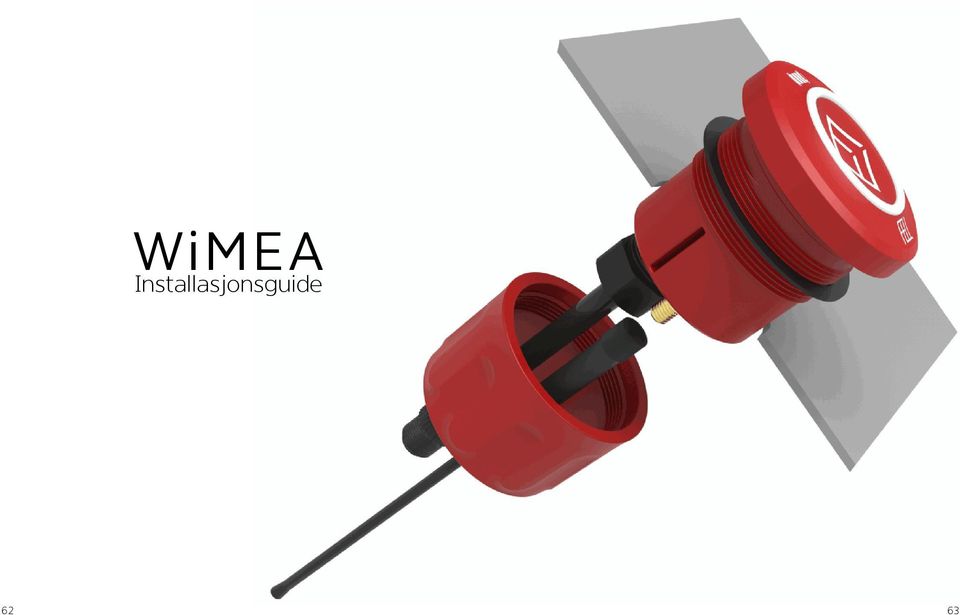
14 Båtenhet - Oversikt WiMEA Installasjonsguide 1. Skru av mutteren på Båtenheten 2. Skru på den eksterne antennen på antennekonnektoren under Båtenheten. 3. Bor et 52mm hull til Båtenheten i ditt dashbord. Bruk standard 52mm hullkopp til å bore hullet. MERK: Påse at det ikke bores gjennom kabler eller utstyr som måtte befinne seg på baksiden av dashbordet. 4. Før Båtenhetens kabel og antenne inn i hullet og plasser Båtenheten i dashbordet. Påse at gummipakningen ligger an på dashbordet under din Båtenhet (se side 62 og 63). 5. Når du plasserer båtenheten, pass på at batteriindikatoren er plassert klokka 12 og FELL-logoen er plassert klokka Skru mutteren til Båtenheten på fra baksiden med håndkraft for å feste den skikkelig. 7. Fest tilkoblingskabelen til kabelen bak på båtenheten ved å skru sammen de to 5-pin konnektorene på kabelen fra båtenheten og tilkoblingskabelen
. 5.")
15 MERK: Båtenheten burde installeres i dashbordet eller så nære førerposisjonen som mulig. MERK: Det kan være lettere å koble til Signalkabelen før Båtenheten festes helt i dashbordet. Koble Signalkabelen som beskrevet i avsnittet «Koble ledningene», på side 68. Deretter koble sammen kabelen bak på Båtenheten med Signalkabelen. Unnlatelse av å følge disse instruksjonene kan medføre brann, elektrisk sjokk eller annen skade på person og materiell. MERK Vi anbefaler at installasjonen av WiMEA i din båt gjøres av en profesjonell fagperson kjent med elektriske koblinger. Dette for å forhindre funksjonsfeil relatert til installasjon

16 Koble ledningene MERK: Ikke ta på eller kutt noen ledningen før du er helt sikker på at båtens hovedbryter står AV. Skru hovedbryteren tilbake til PÅ, kun etter du er ferdig med all kobling og kutting av ledninger. Påse at alle ledninger og tilkoblingspunkter er frie for korrosjon før de kobles

17 Koble til spenningskilde (10 32Vdc) 1. Bruk et testlys eller multimeter for å sjekke polariteten til spenningskilden. 2. Koble rød (+ eller positiv) ledning til den positive terminalen. (Hvis du bruker en sikringsholder i båten, koble gjennom en 1A sikring slik som vist i bildet under). 3. Koble den svarte (- eller jord) ledningen til den negative terminalen. 4. Installer 1A sikring i serie med den rød (+ eller positive) ledningen. 5. Bruk skjøtehylser for korrekt ledningsdiameter (0.75mm). MERK: Bruk en 1 A sikring. Hvis det er nødvendig å forlenge ledningene til strømkilden, bruk minimum 0,75mm2 ledningstykkelse. Du kan koble ledningene direkte til båtens batteri, eller til en sikringsholder hvis båten din har et elektrisk system oppkoblet. Hvis din båt har et NMEA eller NMEA2000 system installert kan du bruke dette som spenningskilde til din WiMEA Båtenhet hvis det er nok strøm tilgjengelig. Vennligst sjekk en relevant kilde for mer informasjon om ditt NMEA-system. NMEA hjemmeside: MERK: Maks spenning for WiMEA Båtenhet er 32Vdc. Ikke overskrid denne spenningen da dette kan ødelegge din WiMEA Båtenhet og vil ugyldiggjøre din garanti

18 Koble til dødmannsknappens signalkabel Før du kobler til signalkablene fra Båtenheten må du teste hvilket prinsipp for dødmannsknapp som brukes av din motorleverandør, enten «Normalt Åpen» eller «Normal Lukket». Signalkablene på WiMEA Båtenheten består av tre kabler. Bare to av disse tre kablene skal kobles til de eksisterende kablene fra dødmannsknappen. Under ser du hvordan du skal gå frem for å finne ut hvilke signalkabler som skal brukes og hvor de skal kobles. Den eksisterende dødmannsknappen i din båt er enten: 1. Normalt Åpen (NÅ) - betyr at dødmannsknappen åpner bryteren og frakobler signalet for å stoppe motoren. 2. Normalt Lukket (NL) betyr at dødmannsknappen lukket bryteren og tilkobler signalet for å stoppe motoren. Det eksisterende systemet har 2 ledninger som er koblet til den mekaniske bryteren (bryteren som brukes til den røde snoren) som er montert i ditt dashbord, kontrollboks eller på motor. For å koble til WiMEA Båtenhet må du først kutte og avmantle ledningene fra den eksisterende dødmannsknappen som vist under: MERK: FELLES - Grå - Denne brukes alltid når dødmannsknappen skal kobles til. 2. Normalt Åpen(NÅ) Blå Brukes når ditt eksisterende system er Normalt Åpent. 3. Normalt Lukket(NL) Oransje Brukes når ditt eksisterende system er Normalt Lukket. Prinsippet for bryteren i dødmannsknappen varierer mellom de forskjellige båtleverandørene, og forskjellige årstall. Noen eksisterende dødmannsknapper har 3 ledninger, men her trenger du kun å bruke to av disse som beskrevet i manualen. Den eksisterende mekaniske bryteren med 3 ledninger er kompatibel med både Normalt Åpen og Normalt Lukket, slik som WiMEA Båtenhet. Etter avmantling av de to ledningene, fortsett med å teste bryterprinsippet i din dødmannsknapp som beskrevet under. Se avsnittet om Koblingsskjema på side 77, for oversikt over tilkoblingene. MERK 5mm Den grå ledningen på Signalkabelen fra WiMEA Båtenhet er FELLES, og brukes for å tilkoble en av de eksisterende signalkablene til dødmannsknappen uavhengig av hvilket prinsipp for dødmannsknapp som finnes i din båt. 73
 - betyr at dødmannsknappen åpner bryteren og frakobler signalet for å stoppe motoren. 2.")
19 Testing av prinsipp for dødmannsknapp (Normalt Åpen / Normalt Lukket) Teste med multimeter Du kan teste prinsippet ved å koble et multimeter til begge kablene fra den eksisterende dødmannsknappen og setter multimeteret til å måle motstand. Se side 75 for illustrasjon. Hvis du måler uendelig motstand(brudd) Du har en Normalt Åpen dødmannsknapp Bruk den Blå og den Grå ledningen for å koble WiMEA Båtenhet til de eksisterende ledningene i din båt. Se koblingsskjema for Normalt Åpen på side 77. Hvis du måler svært lite eller 0 motstand(kortslutning) Du har en Normalt Lukket dødmannsknapp Bruk den Blå og den Oransje ledningen for å koble WiMEA Båtenhet til de eksisterende ledningene i din båt. Se koblingsskjema for Normalt Lukket på side

20 Test med de eksisterende ledningene Koblingsskjema 1. Pass på at de eksisterende ledningene til dødmannsknappen ikke er i kontakt etter at du har kuttet og avmantlet. 2. Sjekk at girspaken er i nøytral. Du skal nå forsøke å starte motoren for å finne ut hvilket prinsipp for dødmannsknapp du har i din båt. 3. Forsøk å starte motoren som normalt. Har du drasnor og ikke tenning vil dødmannsknappen normalt være din stoppknapp. Dersom motoren starter kan du stoppe motoren igjen ved å ved å føre de to signalledningene til motorens dødmannknapp mot hverandre. Pass på å ikke ta på ledningene, ettersom disse kan være strømførende. 4. Resultat: Motoren starter ikke: Du har en Normalt Åpen dødmannsknapp Bruk den Blå og den Grå ledningen for å koble WiMEA Båtenhet til de eksisterende ledningene i din båt. Se koblingsskjema for Normalt Åpen på side 77. Motoren starter: Du har en Normalt Lukket dødmannsknapp Bruk den Oransje og den Grå ledningen for å koble WiMEA Båtenhet til de eksisterende ledningene i din båt. Se koblingsskjema for Normalt Lukket på side 77. Fra WiMEA Båtenhet 5-pin IP67 kontakt Normalt Åpen Rød Sort Grå Blå Oransje Sikring 1 A Batteri VDC Normalt Åpen Normalt Lukket Sikring 1 A Batteri VDC Fra eksisterende kabel til dødmannsknapp Fra WiMEA Båtenhet 5-pin IP67 kontakt Rød Sort Grå Blå Oransje Normalt Lukket Fra eksisterende kabel til dødmannsknapp 76 77

21 Konfigurasjon med flere motorer Hvis du har flere motorer på din båt og båten allerede har en dødmannsknapp kan du koble Signalkablene som vist på side 77, til de to eksisterende kablene for dødmannsknappen i din båt. Det kan hende du ser at ledningene består av en splitter. Det er viktig at denne splitteren beholdes da det er denne som sørger for at alle motorer får samme stoppsignal. Din WiMEA Båtenhet må kobles over denne splitteren, dvs. på samme punkt i kretsen som din eksisterende dødmannsknapp var tilkoblet. MERK: Hvis du har flere motorer men ikke en eksisterende dødmannsknapp, må det installeres ledninger og splitter fra din motorfabrikant. Vennligst kontakt din lokale båtforhandler eller verksted for mer informasjon. Installere WiMEA i en metallbåt Hvis ditt dashbord er laget av ledende materiale slik som metall, kan de trådløse signalene fra WiMEA forringes. Hvor mye signalene forringes vil variere fra båt til båt og må testet for hvert enkelt tilfelle. Hvis signalet er svært dårlig kan du installere en separat ekstern antenne utenfor ditt dashbord for å øke signalstyrken. Vennligst kontakt FELL support på for mer informasjon
22
WiMEA. Owner`s Manual D Ø D M A N N S K N A S L Ø R Å D W I R E L E C T I S W
 T P H WiMEA Owner`s Manual R Å D S L Ø D Ø D M A N N S K N A P W I R E L E S S K I L L I S W C T FELL AS, Nedre Storgate 46, N-3015, Drammen, Norway. FELL, WiMEA, WiMEA8 Protocol, WiMEA9 Protocol and its
WiMEA. Owner`s Manual D Ø D M A N N S K N A S L Ø R Å D W I R E L E C T I S W
 T P H WiMEA Owner`s Manual R Å D S L Ø D Ø D M A N N S K N A P W I R E L E S S K I L L I S W C T FELL AS, Nedre Storgate 46, N-3049, Drammen, Norway. FELL, WiMEA, WiMEA8 Protocol, WiMEA9 Protocol and its
Exercise 1: Phase Splitter DC Operation
 Exercise 1: DC Operation When you have completed this exercise, you will be able to measure dc operating voltages and currents by using a typical transistor phase splitter circuit. You will verify your
INSTALLATION GUIDE FTR Cargo Rack Regular Ford Transit 130" Wheelbase ( Aluminum )
") INSTALLATION GUIDE 1505-FTR Cargo Rack Regular Ford Transit 130" Wheelbase ( Aluminum ) QUICK START GUIDE Phase 1 - Assembly q 1.1 Setup... q 1.2 Cargo Rack Assembly... 3-4 5-6 Phase 2 - Installation q
INSTALLATION GUIDE 1505-FTR Cargo Rack Regular Ford Transit 130" Wheelbase ( Aluminum ) QUICK START GUIDE Phase 1 - Assembly q 1.1 Setup... q 1.2 Cargo Rack Assembly... 3-4 5-6 Phase 2 - Installation q
REMOVE CONTENTS FROM BOX. VERIFY ALL PARTS ARE PRESENT READ INSTRUCTIONS CAREFULLY BEFORE STARTING INSTALLATION
 2011-2014 FORD EXPLORER PARTS LIST Qty Part Description Qty Part Description 1 Bull Bar 2 12mm x 35mm Bolt Plates 1 Passenger/Right Mounting Bracket 2 12mm Nut Plate 1 Driver/Left Mounting Bracket 2 12mm
INSTALLATION GUIDE FTR Cargo Rack Regular Ford Transit 130" Wheelbase ( Aluminum )
") INSTALLATION GUIDE 1505-FTR Cargo Rack Regular Ford Transit 130" Wheelbase ( Aluminum ) QUICK START GUIDE Phase 1 - Assembly q 1.1 Setup... q 1.2 Cargo Rack Assembly... 3-4 5-6 Phase 2 - Installation q
INSTALLATION GUIDE 1505-FTR Cargo Rack Regular Ford Transit 130" Wheelbase ( Aluminum ) QUICK START GUIDE Phase 1 - Assembly q 1.1 Setup... q 1.2 Cargo Rack Assembly... 3-4 5-6 Phase 2 - Installation q
KROPPEN LEDER STRØM. Sett en finger på hvert av kontaktpunktene på modellen. Da får du et lydsignal.
 KROPPEN LEDER STRØM Sett en finger på hvert av kontaktpunktene på modellen. Da får du et lydsignal. Hva forteller dette signalet? Gå flere sammen. Ta hverandre i hendene, og la de to ytterste personene
Windlass Control Panel
 SIDE-POWER 86-08955 Windlass Control Panel v1.0.2 Windlass Systems Installasjon manual SLEIPNER MOTOR AS P.O. Box 519 N-1612 Fredrikstad Norway Tel: +47 69 30 00 60 Fax: +47 69 30 00 70 w w w. s i d e
WiMEA. Owner`s Manual D Ø D M A N N S K N A S L Ø R Å D W I R E L E C T I S W
 T P H WiMEA Owner`s Manual R Å D S L Ø D Ø D M A N N S K N A P W I R E L E S S K I L L I S W C T Package content Introduction English 1. The team behind FELL thank you for engaging in a new and innovative
Slope-Intercept Formula
 LESSON 7 Slope Intercept Formula LESSON 7 Slope-Intercept Formula Here are two new words that describe lines slope and intercept. The slope is given by m (a mountain has slope and starts with m), and intercept
MONTASJEBESKRIVELSE INSTALLATION GUIDE
 MONTASJEBESKRIVELSE INSTALLATION GUIDE ADVARSEL WARNINGS Dette armaturet er et Klasse II produkt som IKKE SKAL TILKOBLES JORD. This device is a class II product: DO NOT CONNECT THE LAMP and the pole to
Start Here USB *CC * *CC * USB USB
 1 USB Start Here USB 11 USB WARNING: To ensure that the software is installed correctly, do not connect the USB cable until step 11. 11 USB 2 a. b. Lower both the paper tray and the print cartridge door.
Midnight BBQ Light USER MANUAL
 Midnight BBQ Light USER MANUAL Instructions The Midnight BBQ Light uses 4 x LR44 / AG13 batteries, included in the package. Unscrew the bottom cover and insert the included batteries and align the battery
User manual English Svenska Norsk
 User manual English Svenska Norsk Copyright This manual is the copyright of CI no 556520-4137. No part of this manual may be revised, copied or transmitted in any way without written permission from CI
SafeRing / SafePlus Retrofit of auxiliary switch S10 for position indication of earthing switch De module
 SafeRing / SafePlus Retrofit of auxiliary switch S10 for position indication of earthing switch De module Installation instructions www.abb.com Document status Responsible RELEASED NODIS Location Date
SafeRing / SafePlus Retrofit of under voltage coil V Module
 SafeRing / SafePlus Retrofit of under voltage coil V Module Installation Instructions www.abb.com Document status Responsible RELEASED NODIS Location Date Name Prepared NODIS 2008-12-15 BJGU/GUSO Checked
Information search for the research protocol in IIC/IID
 Information search for the research protocol in IIC/IID 1 Medical Library, 2013 Library services for students working with the research protocol and thesis (hovedoppgaven) Open library courses: http://www.ntnu.no/ub/fagside/medisin/medbiblkurs
VELKOMMEN INN I DITT NYE TV-UNIVERS. Foto: Jens Haugen / ANTI
 VELKOMMEN INN I DITT NYE TV-UNIVERS Foto: Jens Haugen / ANTI I esken / In the box 1 Huawei Q22 tv-dekoder / Huawei Q22 STB 2 3 4 HDMI 2.0-kabel / HDMI 2.0 cable Nettverkskabel / Ethernet cable Strømforsyning
Trådløsnett med. Wireless network. MacOSX 10.5 Leopard. with MacOSX 10.5 Leopard
 Trådløsnett med MacOSX 10.5 Leopard Wireless network with MacOSX 10.5 Leopard April 2010 Slå på Airport ved å velge symbolet for trådløst nettverk øverst til høyre på skjermen. Hvis symbolet mangler må
Data Sheet for Joysticks
 Available with Potentiometers or Hall sensors Several handle options Small size at low installation depth The 812 series is available with several different handle options. These small joysticks are recommended
Trådløsnett med Windows XP. Wireless network with Windows XP
 Trådløsnett med Windows XP Wireless network with Windows XP Mai 2013 Hvordan koble til trådløsnettet eduroam med Windows XP Service Pack 3? How to connect to the wireless network eduroam with Windows XP
bondura Multi Tool 200 Hydraulic Ø200mm - Ø320mm user manual - for disassembly
 bondura Multi Tool 200 Hydraulic Ø200mm - Ø320mm user manual - for disassembly 1/ cone sleeve removal demontering av konhylse 2/ pin removal demontering av bolt 3/ additional Ø140mm - Ø195mm tillegg for
Data Sheet for Joysticks
 Available with Potentiometers or Hall sensors Several handle options Small size at low installation depth The 812 series is available with several different handle options. These small joysticks are recommended
Instruksjons manual Instruction manual
 knm Copyright c - 2011 knm Side. 1 BRUK AV UTSTYRET Utstyret er designet for løft, trekk, folding/bøying, kutting, støtteoperasjoner etc, og krever, med sitt høye operasjonstrykk og tunge arbeids last,
Unit Relational Algebra 1 1. Relational Algebra 1. Unit 3.3
 Relational Algebra 1 Unit 3.3 Unit 3.3 - Relational Algebra 1 1 Relational Algebra Relational Algebra is : the formal description of how a relational database operates the mathematics which underpin SQL
SafeRing / SafePlus Retrofit of auxiliary switch S7 & S10 for position indication of load break switch and earthing switch C, F and SI modules
 SafeRing / SafePlus Retrofit of auxiliary switch S7 & S10 for position indication of load break switch and earthing switch C, F and SI modules Installation instructions www.abb.com Document status Responsible
Product Facts. Product code example
 ESAM Smoke control damper for multi Rectangular smoke control damper ESAM is specifically designed for use in multi fire compartment applications as a closing or as an opening damper for smoke extract
SafeRing / SafePlus Retrofit of auxiliary switch S9 for fuse blown indication F module
 SafeRing / SafePlus Retrofit of auxiliary switch S9 for fuse blown indication F module Installation instructions www.abb.com Document status Responsible RELEASED NODIS Location Date Name Prepared NODIS
TB-615 / TB-617 Wireless slim keyboard. EN User guide SE Användarhandledning FI Käyttöohje DK Brugervejledning NO Bruksanvisning
 TB-615 / TB-617 Wireless slim keyboard EN User guide SE Användarhandledning FI Käyttöohje DK Brugervejledning NO Bruksanvisning EN User guide You have bought a wireless keyboard to use with Windows XP,
Monteringsanvisning Installation manual Taksokkel for LHH og CareLite Ceiling mount for LHH and CareLite
 Monteringsanvisning Installation manual Taksokkel for LHH og CareLite Ceiling mount for LHH and CareLite Art.nr. 05-900-573-00. Page 1 of 9 Norsk Monteringsanvisning taksokkel Denne monteringsmanualen
Endelig ikke-røyker for Kvinner! (Norwegian Edition)
") Endelig ikke-røyker for Kvinner! (Norwegian Edition) Allen Carr Click here if your download doesn"t start automatically Endelig ikke-røyker for Kvinner! (Norwegian Edition) Allen Carr Endelig ikke-røyker
Endelig ikke-røyker for Kvinner! (Norwegian Edition) Allen Carr Click here if your download doesn"t start automatically Endelig ikke-røyker for Kvinner! (Norwegian Edition) Allen Carr Endelig ikke-røyker
Eksamen KVT2002 Elenergi og automatiseringssystem/systemer. Programområde: Kulde- og varmepumpeteknikk. Nynorsk/Bokmål
 Eksamen 01.06.2016 KVT2002 Elenergi og automatiseringssystem/systemer Programområde: Kulde- og varmepumpeteknikk Nynorsk/Bokmål Nynorsk Eksamensinformasjon Eksamenstid Hjelpemiddel Eksamen varer i 4 timar.
Han Ola of Han Per: A Norwegian-American Comic Strip/En Norsk-amerikansk tegneserie (Skrifter. Serie B, LXIX)
") Han Ola of Han Per: A Norwegian-American Comic Strip/En Norsk-amerikansk tegneserie (Skrifter. Serie B, LXIX) Peter J. Rosendahl Click here if your download doesn"t start automatically Han Ola of Han Per:
Han Ola of Han Per: A Norwegian-American Comic Strip/En Norsk-amerikansk tegneserie (Skrifter. Serie B, LXIX) Peter J. Rosendahl Click here if your download doesn"t start automatically Han Ola of Han Per:
Trigonometric Substitution
 Trigonometric Substitution Alvin Lin Calculus II: August 06 - December 06 Trigonometric Substitution sin 4 (x) cos (x) dx When you have a product of sin and cos of different powers, you have three different
AC10. Brukermanual Brugsanvisning Bruksanvisning User Manual. Spenningsdetektor Voltage Detector. English Norsk
 Spenningsdetektor Voltage Detector Brukermanual Brugsanvisning Bruksanvisning User Manual English Norsk ELIT AS - 2010 Innhold: 1. Generelle applikasjoner. 2. Beskrivelse av instrumentet. 3. Sikkerhetsinformasjon
Norsk (English below): Guide til anbefalt måte å printe gjennom plotter (Akropolis)
: Guide til anbefalt måte å printe gjennom plotter (Akropolis)") Norsk (English below): Guide til anbefalt måte å printe gjennom plotter (Akropolis) 1. Gå til print i dokumentet deres (Det anbefales å bruke InDesign til forberedning for print) 2. Velg deretter print
Norsk (English below): Guide til anbefalt måte å printe gjennom plotter (Akropolis) 1. Gå til print i dokumentet deres (Det anbefales å bruke InDesign til forberedning for print) 2. Velg deretter print
Data Sheet for Joysticks
 Contactless Hall Sensors Optionally with Pushbutton function in handle Mounting option Threaded housing Waterproof, IP class 68 (1 metre) / IP69K The TRY14 series offers proportional miniature-size thumb
Safering / Safeplus Retrofit of Ronis key for disconnector Interlock type EL11AP V and Sv modules
 Safering / Safeplus Retrofit of Ronis key for disconnector Interlock type EL11AP V and Sv modules Installation instructions www.abb.com Document status Responsible RELEASED NODIS Location Date Name Prepared
Fitting instruction. devi-pipeheat / devi-flexheat Assembly between cold tail and selflimiting. Montering av tilledning på selvbegrensende varmekabel
 GB/NO Fitting instruction devi-pipeheat / devi-flexheat Assembly between cold tail and selflimiting heating cable Item no. 19806415 Montering av tilledning på selvbegrensende varmekabel Art. nr. 19806415
ELSEMA 1, 2, 4-Channel 27MHz Transmitter FMT312E, FMT31202E, FMT31204E
 FMT-312E, FMT-31202E, FMT-31204E 12V 1Watt 27MHz Transmitter Features 3 versions available 1-channel (FMT-312E), 2-channel (FMT- 31202E) and 4-channel (FMT-31204E) 1 Watt Transmitter with current consumption
Mounting the electrically elevating legrest
 ASSEMBLY INSTRUCTION Mounting the electrically elevating legrest EN NO 9000A ..8 9000 Mounting the electrically elevating legrest Preparation Note! Switch off the wheelchair via remote control. Instructions
IMPORTANT! HOLD ON THIS DOCUMENT FOR LATER REFERENCE! READ CAREFULLY! VIKTIG! BEHOLD DETTE DOKUMENTET FOR FREMTIDIG BRUK! LES NØYE IGJENNOM!
 GB IMPORTANT! HOLD ON THIS DOCUMENT FOR LATER REFERENCE! READ CAREFULLY! NOR VIKTIG! BEHOLD DETTE DOKUMENTET FOR FREMTIDIG BRUK! LES NØYE IGJENNOM! Produktmål, materiale: 135x77x72 cm Furu Proper use This
Justeringsanvisninger finnes på de to siste sidene.
 d Montering av popup spredere Justeringsanvisninger finnes på de to siste sidene. Link til monteringsfilm på youtube: http://youtu.be/bjamctz_kx4 Hver spreder har montert på en "svinkobling", det vil si
SafeRing / SafePlus Retrofit of auxiliary switch S9 for relay trip indication V module
 SafeRing / SafePlus Retrofit of auxiliary switch S9 for relay trip indication V module Installation instructions www.abb.com Document status Responsible RELEASED NODIS Location Date Name Prepared NODIS
Perpetuum (im)mobile
mobile") Perpetuum (im)mobile Sett hjulet i bevegelse og se hva som skjer! Hva tror du er hensikten med armene som slår ut når hjulet snurrer mot høyre? Hva tror du ordet Perpetuum mobile betyr? Modell 170, Rev.
Perpetuum (im)mobile Sett hjulet i bevegelse og se hva som skjer! Hva tror du er hensikten med armene som slår ut når hjulet snurrer mot høyre? Hva tror du ordet Perpetuum mobile betyr? Modell 170, Rev.
The regulation requires that everyone at NTNU shall have fire drills and fire prevention courses.
 1 The law The regulation requires that everyone at NTNU shall have fire drills and fire prevention courses. 2. 3 Make your self familiar with: Evacuation routes Manual fire alarms Location of fire extinguishers
SHORE POWER CONVERTER LIST 2018
 2018 POWER AT YOUR CONTROL Shore cord capacities These tables provide a approximate indication of the amount of kva capacity of different amperage shore cords at common worldwide voltages. Use these tables
MID-TERM EXAM TDT4258 MICROCONTROLLER SYSTEM DESIGN. Wednesday 3 th Mars Time:
 Side 1 av 8 Norwegian University of Science and Technology DEPARTMENT OF COMPUTER AND INFORMATION SCIENCE MID-TERM EXAM TDT4258 MICROCONTROLLER SYSTEM DESIGN Wednesday 3 th Mars 2010 Time: 1615-1745 Allowed
Sitronelement. Materiell: Sitroner Galvaniserte spiker Blank kobbertråd. Press inn i sitronen en galvanisert spiker og en kobbertråd.
 Materiell: Sitronelement Sitroner Galvaniserte spiker Blank kobbertråd Press inn i sitronen en galvanisert spiker og en kobbertråd. Nå har du laget et av elementene i et elektrisk batteri! Teori om elektriske
EMS 1. Music Streamer. Owner's Manual
 EMS 1 Music Streamer Owner's Manual EN N 2 ENG About the EMS 1 Electrocompaniet Music Streamer This unit is designed to work with the Electrocompaniet PD 1 DAC only. A radio link is established between
Data Sheet for Joysticks
 Up to 3 axes Spring return, friction clutch optionally Sealed up to IP63 Multifunction handle for additional functions, e.g. switches, rockers, deadman paddle Also available with USB- or CAN-Bus-Interface
Bytte til split Collin Lanyard RSL. Obligatorisk - alle rigger skal ha dette montert ved hopping etter 01.01.2015.
 S e r v i c e o r d r e M a t e r i e l l Materiellsjef F/NLF kommuniserer pålegg omkring forhold som ansees som vesentlige for å oppnå de målsettinger som er satt for materiellarbeidet via denne Service
- Vennlig hilsen gründerne bak retyre
 Etter to år med utvikling og testing er retyre endelig klar for å møte den norske vinteren. Det begynte med en idé om en enkel sykkelkjetting, og endte opp med verdens første modulære sykkeldekk. Vi håper
SERVICE BULLETINE 2008-4
 S e r v i c e b u l l e t i n e M a t e r i e l l Materiellsjef F/NLF kommuniserer påminnelse omkring forhold som ansees som vesentlige for å orientere om viktige materiellforhold. Målgruppen for Servicbulletinen
Neural Network. Sensors Sorter
 CSC 302 1.5 Neural Networks Simple Neural Nets for Pattern Recognition 1 Apple-Banana Sorter Neural Network Sensors Sorter Apples Bananas 2 Prototype Vectors Measurement vector p = [shape, texture, weight]
Trådløsnett med Windows Vista. Wireless network with Windows Vista
 Trådløsnett med Windows Vista Wireless network with Windows Vista Mai 2013 Hvordan koble til trådløst nettverk eduroam med Windows Vista? How to connect to the wireless networkeduroam with Windows Vista?
Smart High-Side Power Switch BTS730
 PG-DSO20 RoHS compliant (green product) AEC qualified 1 Ω Ω µ Data Sheet 1 V1.0, 2007-12-17 Data Sheet 2 V1.0, 2007-12-17 Ω µ µ Data Sheet 3 V1.0, 2007-12-17 µ µ Data Sheet 4 V1.0, 2007-12-17 Data Sheet
Replacing the batteries
 ASSEMBLY INSTRUCTION Replacing the batteries EN NO 9010189A 5.2.14 9010189 Replacing the batteries Preparation Switch off the wheelchair via the remote control. Remove the fuses from the battery compartment
5 E Lesson: Solving Monohybrid Punnett Squares with Coding
 5 E Lesson: Solving Monohybrid Punnett Squares with Coding Genetics Fill in the Brown colour Blank Options Hair texture A field of biology that studies heredity, or the passing of traits from parents to
Brukerveiledning. Rolltalk PowerArm. Rev A NO
 Brukerveiledning Rolltalk PowerArm Rev A NO MONTERING Motoren festes med 4 skruer M6 x 16 til en solid brakett montert på stolen. Braketten må forarbeides / tilpasses i hvert tilfelle, med hensyn til stoltype
Hvordan føre reiseregninger i Unit4 Business World Forfatter:
 Hvordan føre reiseregninger i Unit4 Business World Forfatter: dag.syversen@unit4.com Denne e-guiden beskriver hvordan du registrerer en reiseregning med ulike typer utlegg. 1. Introduksjon 2. Åpne vinduet
Dagens tema: Eksempel Klisjéer (mønstre) Tommelfingerregler
 Tommelfingerregler") UNIVERSITETET I OSLO INF1300 Introduksjon til databaser Dagens tema: Eksempel Klisjéer (mønstre) Tommelfingerregler Institutt for informatikk Dumitru Roman 1 Eksempel (1) 1. The system shall give an overview
UNIVERSITETET I OSLO INF1300 Introduksjon til databaser Dagens tema: Eksempel Klisjéer (mønstre) Tommelfingerregler Institutt for informatikk Dumitru Roman 1 Eksempel (1) 1. The system shall give an overview
KAMPANJE APK : APK-5: Skifte pakninger mellom turbo og CCDPF
 KAMPANJE APK-5 20150722: APK-5: Skifte pakninger mellom turbo og CCDPF Berørte modeller for APK-5: Vitara APK416D, totalt 66 biler. Liste med chassisnummer legges ikke ved, bruk Forhandlerweb til å sjekke
FYSMEK1110 Eksamensverksted 23. Mai :15-18:00 Oppgave 1 (maks. 45 minutt)
") FYSMEK1110 Eksamensverksted 23. Mai 2018 14:15-18:00 Oppgave 1 (maks. 45 minutt) Page 1 of 9 Svar, eksempler, diskusjon og gode råd fra studenter (30 min) Hva får dere poeng for? Gode råd fra forelesere
FYSMEK1110 Eksamensverksted 23. Mai 2018 14:15-18:00 Oppgave 1 (maks. 45 minutt) Page 1 of 9 Svar, eksempler, diskusjon og gode råd fra studenter (30 min) Hva får dere poeng for? Gode råd fra forelesere
GYRO MED SYKKELHJUL. Forsøk å tippe og vri på hjulet. Hva kjenner du? Hvorfor oppfører hjulet seg slik, og hva er egentlig en gyro?
 GYRO MED SYKKELHJUL Hold i håndtaket på hjulet. Sett fart på hjulet og hold det opp. Det er lettest om du sjølv holder i håndtakene og får en venn til å snurre hjulet rundt. Forsøk å tippe og vri på hjulet.
Bestille trykk av doktoravhandling Ordering printing of PhD Thesis
 Bestille trykk av doktoravhandling Ordering printing of PhD Thesis Brukermanual / User manual Skipnes Kommunikasjon ntnu.skipnes.no PhD Thesis NTNU LOG IN NOR: Gå inn på siden ntnu.skipnes-wtp.no, eller
Elektronisk innlevering/electronic solution for submission:
 VIKINGTIDSMUSEET Plan- og designkonkurranse/design competition Elektronisk innlevering/electronic solution for submission: Det benyttes en egen elektronisk løsning for innlevering (Byggeweb Anbud). Dette
229 SONATA Manual NO_ENG 1.04
 -SONATA 2 SONATA SONATA Informasjon og sikkerhet ADVARSEL -Bruk bare strømforsyning som er godkjent av COMMidt, for bruk sammen med denne enheten. Bruk av andre typer kan oppheve all godkjenning og garanti,
WÄRTSILÄ MARINE SOLUTION POWER CONVERSION INNOVATIVE LAV- OG NULLUTSLIPPSLØSNINGER OG UTFORDRINGER MED Å FÅ DISSE INN I MARKEDET.
 INNOVATIVE LAV- OG NULLUTSLIPPSLØSNINGER OG UTFORDRINGER MED Å FÅ DISSE INN I MARKEDET. WÄRTSILÄ MARINE SOLUTION POWER CONVERSION INGVE SØRFONN 1 THE FUTURE IS NOW! 2 FROM PRODUCT TO ECOSYSTEM 3 READY
// Translation // KLART SVAR «Free-Range Employees»
 // Translation // KLART SVAR «Free-Range Employees» Klart Svar is a nationwide multiple telecom store, known as a supplier of mobile phones and wireless office solutions. The challenge was to make use
HONSEL process monitoring
 6 DMSD has stood for process monitoring in fastening technology for more than 25 years. HONSEL re- rivet processing back in 990. DMSD 2G has been continuously improved and optimised since this time. All
bondura dual 36 Ø50mm - Ø200mm assembly & inspection manual art rev A
 bondura dual 36 Ø50mm - Ø200mm assembly & inspection manual art. 103803 rev. 27.04.2016 A TABLE OF CONTENT / INNHOLD 1/ assembly montering 2/ technical specifications/torque tekniske data/tiltrekkingsmoment
KAMPANJE APK : APK-8: Bytte bakaksel bolter
 KAMPANJE APK-8 20160222: APK-8: Bytte bakaksel bolter Berørte modeller for APK-8: Vitara APK, S-cross AKK, og Swift AZG. Totalt 454 biler på det norske markedet. Liste med chassisnummer legges ikke ved,
SmartPass Mini User Manual BBNORGE.NO
 SmartPass Mini User Manual BBNORGE.NO Intro Welcome to the usermanual for your SmartPass Mini system. The first time you start the SmartPass you have to request a License. This is to regiser your license
SafeRing / SafePlus Retrofit of capacitive voltage indication type VPIS C, De, F and V Modules
 We reserve all rights in this document and in the information contained therein: Reproduction, use or disclosure to third parties without SafeRing / SafePlus Retrofit of capacitive voltage indication type
RT-U3HDDA USB 3.0 TO SATA ADAPTER. User s Manual. USB 3.0 to SATA Adapter USB 3.0 till SATA Adapter USB 3.0 til SATA Adapter
 RT-U3HDDA USB 3.0 TO SATA ADAPTER User s Manual USB 3.0 to SATA Adapter USB 3.0 till SATA Adapter USB 3.0 til SATA Adapter Introduction Thank you for purchasing this product. In order to obtain optimum
Data Sheet for Joysticks
 Different handle designs available Optionally with Pushbuttons and Deadman Industrial-suited robust design IP classes up to 68 (on request) Several Output Options (analog, CAN J1939, CANopen, USB) The
Profile handbook. for
 Profile handbook for March 2007 Logo For the logo, we have chosen a shape in conformity with the general visual direction. The logo is inspired by the shape of the product, and the circle also creates
NÅR FAGKUNNSKAP & KOMPETANSE TELLER BRUKERMANUAL ELIT AC10 SPENNINGSDETEKTOR USER MANUAL ELIT AC10 VOLTAGE DETECTOR. English Norsk
 NÅR FAGKUNNSKAP & KOMPETANSE TELLER BRUKERMANUAL ELIT AC10 SPENNINGSDETEKTOR USER MANUAL ELIT AC10 VOLTAGE DETECTOR English Norsk WWW.ELIT.NO Innhold: NORSK 1. Generelle applikasjoner. 2. Beskrivelse av
Replacing the tube and/or tyre of a drive wheel, indoor/outdoor
 ASSEMBLY INSTRUCTION Replacing the tube and/or tyre of a drive wheel, indoor/outdoor EN NO 9010182A 5.2.7 9010182 Replacing the tube and/or tyre of a drive wheel, indoor/outdoor Preparation Be sure that
TUSEN TAKK! BUTIKKEN MIN! ...alt jeg ber om er.. Maren Finn dette og mer i. ... finn meg på nett! Grafiske lisenser.
 TUSEN TAKK! Det at du velger å bruke mitt materiell for å spare tid og ha det kjekt sammen med elevene betyr mye for meg! Min lidenskap er å hjelpe flotte lærere i en travel hverdag, og å motivere elevene
Robertson S35 NFU Steering Lever
 Robertson S35 NFU Steering Lever S35 is designed for indoor and outdoor bulkhead mount and made of shock resistant polyxymethylene. The lever has spring loaded return to mid-position. A push button with
TUSEN TAKK! BUTIKKEN MIN! ...alt jeg ber om er.. Maren Finn dette og mer i. ... finn meg på nett! Grafiske lisenser.
 TUSEN TAKK! Det at du velger å bruke mitt materiell for å spare tid og ha det kjekt sammen med elevene betyr mye for meg! Min lidenskap er å hjelpe flotte lærere i en travel hverdag, og å motivere elevene
KAMPANJE AZG : Skifte bolter reimhjul
 KAMPANJE AZG-4 20141009: Skifte bolter reimhjul Berørte modeller: Swift AZG type 3 (produsert i Ungarn) fra 2013 og nyere. (Type 3: Biler med automatisk kjørelys og navigasjon). Kampanjen omfatter totalt
bondura Multi Tool 200
 bondura Multi Tool 200 pin and conical sleeve removal Ø200mm - Ø320mm user manual - for disassembly art. 103807 rev. 16.03.2016 A 1/ bondura 6.6 1.1 conical sleeve removal / demontering av konhylse 1.2
RF Power Capacitors Class1. 5kV Discs
 RF Power Capacitors Class 5kV Discs T H E C E R A M C E X P E R T S RF Power Capacitors Class 5kV Discs The CeramTec Group is a world leader in the design and manufacture of complex electronic ceramic
For at salget skal se organisert ut, er det viktig at klær henges på klesstativene og legges i kassene på en ryddig måte. Da vil du få solgt mer!
 If we are organized in the way we hang clothes on the racks and put clothes in the bins, we ll have a wonderfully organized sale! And you will sell more! With the front of the clothing item facing you,
TUSEN TAKK! BUTIKKEN MIN! ...alt jeg ber om er.. Maren Finn dette og mer i. ... finn meg på nett! Grafiske lisenser.
 TUSEN TAKK! Det at du velger å bruke mitt materiell for å spare tid og ha det kjekt sammen med elevene betyr mye for meg! Min lidenskap er å hjelpe flotte lærere i en travel hverdag, og å motivere elevene
Wonderland 904. Regulerbar seng Electrical adjustable bed. my bed - my wonderland
 Wonderland 904 Regulerbar seng Electrical adjustable bed my bed - my wonderland Lykke til med valget av ditt nye Wonderland produkt. Wonderland produserer individuelt tilpassede sengeløsninger med unike
Tilkoblingsskinner. For kontaktorer og effektbrytere
 Tilkoblingsskinner For kontaktorer og effektbrytere Riktige tilkoblingsskinner gir optimale løsninger I tillegg til design, brukervennlighet og stort funksjonsområde er alle lavspenningsproduktene fra
RF Power Capacitors Class kV Discs with Moisture Protection
 RF Power Capacitors Class 0-20kV Discs with Moisture Protection T H E C E R A M I C E X P E R T S RF Power Capacitors Class 0-20kV Discs with Moisture Protection The CeramTec Group is a world leader in
Den som gjør godt, er av Gud (Multilingual Edition)
") Den som gjør godt, er av Gud (Multilingual Edition) Arne Jordly Click here if your download doesn"t start automatically Den som gjør godt, er av Gud (Multilingual Edition) Arne Jordly Den som gjør godt,
Den som gjør godt, er av Gud (Multilingual Edition) Arne Jordly Click here if your download doesn"t start automatically Den som gjør godt, er av Gud (Multilingual Edition) Arne Jordly Den som gjør godt,
NEOREST Hybrid (Toilet bowl) NEOREST Hybrid. Installation manual. Safety Cautions Precaution before installation. Included parts.
 NEOREST Hybrid. Installation manual. Safety Cautions Precaution before installation. Included parts.") Installation manual NEOREST Hybrid (Toilet bowl) NEOREST Hybrid Safety Cautions Precaution before installation Included parts Part diagram Installation procedure EN Install the product properly according
Installation manual NEOREST Hybrid (Toilet bowl) NEOREST Hybrid Safety Cautions Precaution before installation Included parts Part diagram Installation procedure EN Install the product properly according
FDV Dokumentasjon. ES Maxi varslingsvogn med lastekasse. Produktnavn: Varenummer: Produktspesifikasjon:
 FDV Dokumentasjon Rev. Dato: 14.04.2010 Produktnavn: ES Maxi varslingsvogn med lastekasse Varenummer: 410 161 000 10 Produktspesifikasjon: Varslingsvogn med lyspil og vekselblink. I samsvar med HB062,
Product Manual Produkthåndbok
 BEAM Product Manual Produkthåndbok BEAM Technical Specifications Tekniske Spesifikasjoner Description Product number Mode Voltage Current Vehicle interface Cable length Encapsulation Operating temperature
Software applications developed for the maritime service at the Danish Meteorological Institute
 Software applications developed for the maritime service at the Danish Meteorological Institute Anne Marie Munk Jørgensen (ammj@dmi.dk), Ove Kjær, Knud E. Christensen & Morten L. Mortensen Danish Meteorological
SafeRing / SafePlus Retrofit of opening coil Y1 and auxiliary switch S7 F, C and SI Modules with latched mechanism
 SafeRing / SafePlus Retrofit of opening coil Y1 and auxiliary switch S7 F, C and SI Modules with latched mechanism Installation instructions www.abb.com Document status Responsible RELEASED NODIS Location
SafeRing / SafePlus Retrofit of Y4 or Y5 relay trip coil V Module
 SafeRing / SafePlus Retrofit of Y4 or Y5 relay trip coil V Module Installation instructions www.abb.com Document status Responsible RELEASED NODIS Location Date Name Prepared NODIS 2008-12-15 BJGU/GUSO
Oversikt over I/O tilkoblinger og moduler på modellbyen
 Oversikt over I/O tilkoblinger og moduler på modellbyen (Dette er et vedlegg som tilhører Hoveddokumentet B014-106 HMI løsning med Wanderware 2014). Her er oversikt over alle modulene som er brukt på modellbyen.