PIPESTEC INDUSTRIAL GROUP LIMITED
|
|
|
- Patrik Tønnessen
- 4 år siden
- Visninger:
Transkript


1 Products Pipe Flange Butt Welding Pipe Fittings Forged Pipe Fittings Fasteners Valves Accessaries PIPESTEC INDUSTRIAL GROUP LIMITED Copyright All Rights Reserved.
2 CONTENTS 1. INTRODUCTION Presentation Typical products and materials of typical pipes, fittings and flanges available from stock 2. PIPES - ASME B36.10 AND ASME B36.19 Pipe Schedule Chart in inch and mm versions Dimensions and weights of ASME B36.10 pipes 3. TUBES - ASTM A269 Metric and Fractional sizes 4. BUTT WELD FITTINGS ASME B16.9 AND MSS SP-75 ASME B16.9 Elbows (LR), Tees, Reducers, End caps, Stub-ends, Return bends (LR) ASME B16.28 MSS SP-43 MSS SP-75 Elbows (SR), Return bends (SR) Stub ends type A Elbows (LR), Tees, Reducers, End caps, 5. FLANGES ASME B16.5 MSS SP-44 Weld-neck, Blind, Slip-on, Socket-weld, Lap-Joint, Threaded Weld-neck, Blind API 6A Type 6B and 6BX FORGED FITTINGS ASME B16.11 AND BS3799 ASME B16.11/BS3799 Threaded and socket welding - Elbows, Tees, Crosses, Couplings, Caps, Bushing, Plugs, Nipples, Unions, Welding boss O LETS Manufacturers standard O let types: Buttweld, Elbow, Lateral, Nipple, Insert Branch, Flanged Buttweld, Flanged Nipple WEIGHTS

3 COMPANY PRESENTATION An integrated partner in the value chain How to contact us


4 COMPANY PRESENTATION Qualification to Typical products and materials Products in stock: Material qualities:
5 Types of pipes, fittings and flanges in stock Sizes and material types: The below listed products are typical available from our stock in size range from 0.5 to 24. Larger sizes and other materials may also be available on request, but can in all cases be offered based on new production at mills. Material properties / certification: Material purchased to our stock are manufactured, tested and certified in accordance to specification Typical modified requirements are indicated in tables below. All products are certified to EN10204 type 3.1 Carbon steel - Type 235 Product Standard Grade Class Suppl. requirement Seamless pipe ASTM A106 B S6 Welded pipe ISO 3183 (API 5L) L245 (B) SAWL PSL1 ASTM A672 C60, C70 12, 22 for t>19mm Wrought fitting ASTM A234 WPB S3 Forging/ flange ASTM A105 S4 Chemical: C< 0.20 %; S< %; P< %; CE = C + Mn/6 + (Cr+Mo+V)/5 + (Cu+Ni)/15 < 0.43 Hardness: NACE MR-0175/ ISO compliance Carbon steel - Type 235LT Product Standard Grade Class Suppl. requirement Seamless pipe ASTM A333 6 Welded pipe ASTM A671 CC60, CC70 12, 22 for t>19mm S2, S7, S14 Wrought fitting ASTM A420 WPL6 S51, S53, S59, S69 Forging/ flange ASTM A350 LF2 1 S6, S55 Chemical: Hardness: Impact: C< 0.20 %; S< %; P< %; (+ additional limitations for A333 gr.6) CE = C + Mn/6 + (Cr+Mo+V)/5 + (Cu+Ni)/15 < 0.43 NACE MR-0175/ ISO compliance 27J average/ 20J single at -46 degree C, for thicknesses above 6mm Carbon steel - Type 360LT Product Standard Grade Class Suppl. requirement Seamless pipe ISO 3183 (API 5L) L360N or Q (X52) PSL2 Wrought fitting ASTM A860 WPHY52 Smls & welded S53, S69 Forging/ flange ASTM A694 F52 S55 Chemical: C< 0.20% (C< 0.16% for X52); Mn = %; Si = %; S< 0.025%; P< 0.035%; Ti< 0.05%; Nb< 0.04%; Al< 0.06%; N< 0.015%; V+Nb+Ti< 0.10% CE = C + Mn/6 + (Cr+Mo+V)/5 + (Cu+Ni)/15 < 0.43 Hardness: NACE MR-0175/ ISO compliance Impact: 40J average/ 30J single at -46 degree C, for thicknesses above 6mm High strength, low alloyed steel - Type 4130/4140 Product Standard Grade Class Suppl. requirement Seamless pipe ASTM A519 AISI 4130 Wrought fitting ASTM A234 AISI 4130 Seamless S2 Forging/ flange ASTM A788 AISI 4140 S18 Forging/ flange API 6A 60K (AISI 4130) PSL 3 Chemical: Pipe and fitting: S< 0.015%, P< 0.025% Tensile: Pipe and fitting: Yield (0.2%) > 415MPa, UTS > 620MPa, A5 > 18% A788 forging: Yield (0.2%) > 515MPa, UTS > 690MPa, A5 > 15% Hardness: Pipes, fitings and API 6A forgings: Maximum 250HV10, 237HB or 22HRC A788 forgings: 328HB or 35HRC Impact: 42J average/ 30J single at -30 degree C, for thicknesses above 6mm
6 Austenittic Stainless steel - Type 316/316L Product Standard Grade Class Suppl. requirement Seamless pipe ASTM A312 TP316/ TP316L Welded pipe ASTM A312 TP316/ TP316L ASTM A / 316L 1, 3, 4 and 5 Wrought fitting ASTM A403 WP316/ WP316L S, W, WX Forging/ flange ASTM A182 F316/ F316L Tube ASTM A / 316L Chemical: C< 0.035% Tensile: Yield (0.2%) > 205MPa, UTS > 515MPa, A> 35% Hardness: NACE MR-0175/ ISO compliance Austenittic Stainless steel - Type 6Mo Product Standard Grade Class Suppl. requirement Seamless pipe ASTM A312 UNS S31254* Welded pipe ASTM A358 UNS S31254* 1, 3 and 5 S3 Wrought fitting ASTM A403 WP S31254* S, W, WX Forging/ flange ASTM A182 F44 (S31254)* S56 Tube ASTM A269 UNS S31254* Grades *: Corrosion test: Hardness: UNS N08926 are acceptable in addition to the above grade ASTM G48 method A, 50 degree C / 24h, max 4g/m2 weight loss, no pitting NACE MR-0175/ ISO compliance Ferritic/Austenittic Stainless steel - Type 22Cr duplex Product Standard Grade Class Suppl. requirement Seamless pipe ASTM A790 UNS S31803* Welded pipe ASTM A928 UNS S31803* 1, 3 and 5 S3 Wrought fitting ASTM A815 UNS S31803* S, W, WX S7 Forging/ flange ASTM A182 F51* S56 Tube ASTM A789 UNS S31803* Grades *: UNS S32205/ F60 are acceptable in addition to the above grade Chemical: N = %; PREN > 34% Impact: 45J average/ 35J single at -46 degree C, for thicknesses above 6mm Corrosion test: ASTM G48 method A, 25 degree C / 24h, max 4g/m2 weight loss, no pitting Hardness: Max 290 HV10 (or 28HRC or 271HB) Micro: Ferrite level 35-55% for base, 35-65% for weld areas. No phases or precipitates. Ferritic/Austenittic Stainless steel - Type 25Cr duplex Product Standard Grade Class Suppl. requirement Seamless pipe ASTM A790 UNS S32760* Welded pipe ASTM A928 UNS S32760* 1, 3 and 5 S3 Wrought fitting ASTM A815 UNS S32760* S, W, WX S7 Forging/ flange ASTM A182 F55 (S32760)* S56 Tube ASTM A789 UNS S32760* Grades*: UNS S32750/F53 and UNS S32550 are acceptable in addition to the above grade Chemical: PRE (Cr + 3.3xMo + 16xN) > 40.0 Tensile: Yield (0.2%) > 550MPa, UTS > 750MPa, A5 > 25% Impact: 45J average/ 35J single at -46 degree C, for thicknesses above 6mm Corrosion test: ASTM G48 method A, 50 degree C / 24h, max 4g/m2 weight loss, no pitting Hardness: Max 330 HV10 (or 32HRC or 301HB) Micro: Ferrite level 35-55% for base, 35-65% for weld areas. No phases or precipitates.
7 High strength Austenittic Stainless steel - Type Superaustenite Product Standard Grade Class Suppl. requirement Welded pipe ASTM A358 UNS S , 3 S3 Wrought fitting ASTM A403 UNS S34566 S, WX Forging/ flange ASTM A182 F49 S56 Tensile: Hardness: Corrosion test: Yield (0.2%) > 415MPa, UTS > 795MPa Max 34HRC ASTM G48 method A, 50 degree C / 24h, max 4g/m2 weight loss, no pitting Copper alloy - Type CuNi 90/10 Product Standard Grade Class Suppl. requirement Seamless pipe ASTM B466 UNS C70600 Welded pipe ASTM B467 UNS C70600 Wrought fitting UNS C70600 Forging/flange UNS C70600 Material purchased to our stock are modified to Norsok data sheet MDS K01, e.g: Dimensions: In accordance to respective EEMUA standards - No.144, 145, 146 Nickel alloy - Type Inconel 625 Product Standard Grade Class Suppl. requirement Seamless pipe ASTM B444 UNS N06625 Welded pipe ASTM B705 UNS N Wrought fitting ASTM B366 UNS N06625 S3 Forging/flange ASTM B564 UNS N06625 S5.3 Tube ASTM B444 UNS N06625 Material purchased to our stock are modified to Norsok data sheet MDS N01, e.g: Heat treatment: All products shall be annealed


8 PIPES ASME B36.10 ASME B36.19
9 ASME B36.19-B36.10 pipe dimensions in inch and weights in kg NPS O.D. (INCH) (INCH) 5 S 5 10 S STD XS XXS 40 S 80 S 1/8 0,405 0,049 0,057 0,068 0,095 0,3 0,3 0,4 0,5 1/4 0,540 0,065 0,073 0,088 0,119 0,5 0,5 0,6 0,8 3/8 0,675 0,065 0,073 0,091 0,126 0,6 0,7 0,9 1,1 1/2 0,840 0,065 0,083 0,095 0,109 0,147 0,187 0,294 0,8 1,0 1,1 1,3 1,6 2,0 2,6 3/4 1,050 0,065 0,083 0,095 0,113 0,154 0,219 0,308 1,0 1,3 1,4 1,7 2,2 2,9 3,7 1 1,315 0,065 0,109 0,114 0,133 0,179 0,250 0,358 1,3 2,1 2,2 2,5 3,3 4,3 5, ,660 0,065 0,109 0,117 0,140 0,191 0,250 0,382 1,7 2,7 2,9 3,4 4,5 5,7 7, ,900 0,065 0,109 0,125 0,145 0,200 0,281 0,400 1,9 3,2 3,5 4,1 5,5 7,4 9,7 2 2,375 0,065 0,109 0,125 0,154 0,218 0,344 0,436 2,4 4,0 4,5 5,5 7,6 11,1 13, ,875 0,083 0,120 0,188 0,203 0,276 0,375 0,552 3,8 5,3 8,0 8,6 11,4 14,0 20,4 3 3,500 0,083 0,120 0,188 0,216 0,300 0,438 0,600 4,6 6,5 9,9 11,3 15,3 21,4 27, ,000 0,083 0,120 0,188 0,226 0,318 5,2 7,4 11,4 13,6 18,6 4 4,500 0,083 0,120 0,188 0,237 0,337 0,438 0,531 0,674 5,8 8,4 12,9 16,1 22,3 28,3 33,5 41,0 5 5,563 0,109 0,134 0,258 0,375 0,500 0,625 0,750 9,5 11,6 21,8 31,0 40,3 49,1 57,4 6 6,625 0,109 0,134 0,280 0,432 0,562 0,719 0,864 11,3 13,8 28,3 42,6 54,2 67,6 79,2 8 8,625 0,109 0,148 0,250 0,277 0,322 0,406 0,500 0,594 0,719 0,812 0,906 0,875 14,8 20,0 33,3 36,8 42,6 53,1 64,6 75,9 90,4 100,9 111,3 107, ,75 0,134 0,165 0,250 0,307 0,365 0,500 0,500 0,594 0,719 0,844 1,000 1,125 1,000 22,6 27,8 42,4 51,8 60,3 81,6 81,6 96,0 114,8 133,1 155,2 172,3 155, ,75 0,156 0,180 0,250 0,330 0,375 0,406 0,562 0,500 0,688 0,844 1,000 1,125 1,312 1,000 31,3 36,0 49,7 65,2 73,9 79,7 109,0 97,4 132,1 159,9 187,0 208,1 238,8 187, ,00 0,156 0,188 0,250 0,312 0,375 0,375 0,438 0,594 0,500 0,750 0,938 1,094 1,250 1,406 34,4 41,3 54,7 67,9 81,3 81,3 94,6 126,7 107,4 158,1 195,0 224,7 253,5 281, ,00 0,165 0,188 0,250 0,312 0,375 0,375 0,500 0,656 0,500 0,844 1,031 1,219 1,438 1,594 41,6 47,3 62,6 77,8 93,3 93,3 123,3 160,1 123,3 203,5 245,6 286,6 333,2 365, ,00 0,165 0,188 0,250 0,312 0,438 0,375 0,562 0,750 0,500 0,938 1,156 1,375 1,562 1,781 46,8 53,3 70,6 87,7 122,4 105,2 155,8 205,7 139,2 254,6 309,6 363,6 408,3 459, ,00 0,188 0,218 0,250 0,375 0,500 0,375 0,594 0,812 0,500 1,031 1,281 1,500 1,750 1,969 59,3 68,6 78,6 117,2 155,1 117,2 183,4 247,8 155,1 311,2 381,5 441,5 508,1 564, ,00 0,188 0,218 0,250 0,375 0,500 0,375 0,875 0,500 1,125 1,375 1,625 1,875 2,125 65,2 75,5 86,5 129,1 171,1 129,1 299,3 171,1 373,8 451,5 527,0 600,6 672, ,00 0,218 0,250 0,250 0,375 0,562 0,375 0,688 0,969 0,500 1,219 1,531 1,812 2,062 2,344 82,5 94,5 94,5 141,1 209,6 141,1 255,4 355,3 187,1 442,1 547,7 640,0 720,2 808, ,00 0,312 0,500 0,375 0, ,4 202,7 152,9 202, ,00 0,312 0,500 0,625 0,375 0, ,2 218,7 271,2 164,9 218, ,00 0,250 0,312 0,312 0,500 0,625 0,375 0, ,3 147,4 147,3 324,7 292,2 176,8 324, ,00 0,312 0,500 0,625 0,375 0,688 0, ,2 250,7 316,9 188,8 342,9 250, ,00 0,312 0,500 0,625 0,375 0,688 0, ,2 266,6 332,1 200,3 365,0 266, ,00 0,312 0,500 0,625 0,375 0,750 0, ,0 282,3 351,7 212,6 420,4 282,3 NOTE: IDENTICAL to 5 s IDENTICAL to 10 s IDENTICAL to 40 s & std Light blue values are wall thicknesses in inch, darker blue values are weights in kg/m. Specific steel weight used for calculation is 8.0, Titanium weight is approximately 57% of the table values, IDENTICAL to 80 s & XS NPS = Nominal Pipe Size - description of pipe size in inch, O.D = Outside Diameter of pipe, Sch5S and 10S do not permit threading according to ANSI B1.20.1, Sch40S and 80S in the table are applicable up to and including 12.
10 ASME B36.19-B36.10 pipe dimensions in mm and weights in kg DN NPS O.D. (MM) (INCH) (MM) 5 S 5 10 S STD XS XXS 40 S 80 S - 1/8 10,3 1,24 1,45 1,73 2,41 0,3 0,3 0,4 0,5-1/4 13,7 1,65 1,85 2,24 3,02 0,5 0,5 0,6 0,8 10 3/8 17,1 1,65 1,85 2,31 3,20 0,6 0,7 0,9 1,1 15 1/2 21,3 1,65 2,11 2,41 2,77 3,73 4,75 7,47 0,8 1,0 1,1 1,3 1,6 2,0 2,6 20 3/4 26,7 1,65 2,11 2,41 2,87 3,91 5,56 7,82 1,0 1,3 1,4 1,7 2,2 2,9 3, ,4 1,65 2,77 2,90 3,38 4,55 6,35 9,09 1,3 2,1 2,2 2,5 3,3 4,3 5, ,2 1,65 2,77 2,97 3,56 4,85 6,35 9,70 1,7 2,7 2,9 3,4 4,5 5,7 7, ,3 1,65 2,77 3,18 3,68 5,08 7,14 10,15 1,9 3,2 3,5 4,1 5,5 7,4 9, ,3 1,65 2,77 3,18 3,91 5,54 8,74 11,07 2,4 4,0 4,5 5,5 7,6 11,1 13, ,0 2,11 3,05 4,78 5,16 7,01 9,53 14,02 3,8 5,3 8,0 8,6 11,4 14,0 20, ,9 2,11 3,05 4,78 5,49 7,62 11,13 15,24 4,6 6,5 9,9 11,3 15,3 21,4 27, ,6 2,11 3,05 4,78 5,74 8,08 5,2 7,4 11,4 13,6 18, ,3 2,11 3,05 4,78 6,02 8,56 11,13 13,49 17,12 5,8 8,4 12,9 16,1 22,3 28,3 33,5 41, ,3 2,77 3,40 6,55 9,53 12,70 15,88 19,05 9,5 11,6 21,8 31,0 40,3 49,1 57, ,3 2,77 3,40 7,11 10,97 14,27 18,26 21,95 11,3 13,8 28,3 42,6 54,2 67,6 79, ,1 2,77 3,76 6,35 7,04 8,18 10,31 12,70 15,09 18,26 20,62 23,01 22,23 14,8 20,0 33,3 36,8 42,6 53,1 64,6 75,9 90,4 100,9 111,3 107, ,0 3,40 4,19 6,35 7,80 9,27 12,70 12,70 15,09 18,26 21,44 25,40 28,58 25,40 IDENTICAL to 5 s IDENTICAL to 10 s 22,6 27,8 42,4 51,8 60,3 81,6 81,6 96,0 114,8 133,1 155,2 172,3 155, ,8 3,96 4,57 6,35 8,38 9,53 10,31 14,27 12,70 17,48 21,44 25,40 28,58 33,32 25,40 31,3 36,0 49,7 65,2 73,9 79,7 109,0 97,4 132,1 159,9 187,0 208,1 238,8 187, ,6 3,96 4,78 6,35 7,92 9,53 9,53 11,13 15,09 12,70 19,05 23,83 27,79 31,75 35,71 34,4 41,3 54,7 67,9 81,3 81,3 94,6 126,7 107,4 158,1 195,0 224,7 253,5 281, ,4 4,19 4,78 6,35 7,92 9,53 9,53 12,70 16,66 12,70 21,44 26,19 30,96 36,53 40,49 41,6 47,3 62,6 77,8 93,3 93,3 123,3 160,1 123,3 203,5 245,6 286,6 333,2 365, ,19 4,78 6,35 7,92 11,13 9,53 14,27 19,05 12,70 23,83 29,36 34,93 39,67 45,24 46,8 53,3 70,6 87,7 122,4 105,2 155,8 205,7 139,2 254,6 309,6 363,6 408,3 459, ,78 5,54 6,35 9,53 12,70 9,53 15,09 20,62 12,70 26,19 32,54 38,10 44,45 50,01 59,3 68,6 78,6 117,2 155,1 117,2 183,4 247,8 155,1 311,2 381,5 441,5 508,1 564, ,78 5,54 6,35 9,53 12,70 9,53 22,23 12,70 28,58 34,93 41,28 47,63 53,98 65,2 75,5 86,5 129,1 171,1 129,1 299,3 171,1 373,8 451,5 527,0 600,6 672, ,54 6,35 6,35 9,53 14,27 9,53 17,48 24,61 12,70 30,96 38,89 46,02 52,37 59,54 82,5 94,5 94,5 141,1 209,6 141,1 255,4 355,3 187,1 442,1 547,7 640,0 720,2 808, ,92 12,70 9,53 12,70 127,4 202,7 152,9 202, ,92 12,70 15,88 9,53 12,70 137,2 218,7 271,2 164,9 218, ,35 7,92 7,92 12,70 15,88 9,53 12,70 118,3 147,4 147,3 234,7 292,2 176,8 234, ,92 12,70 15,88 9,53 17,48 12,70 157,2 250,7 316,9 188,8 342,9 250, ,92 12,70 15,88 9,53 17,48 12,70 167,2 266,6 332,1 200,3 365,0 266,6 IDENTICAL to 40 s & std IDENTICAL to 80 s & XS ,92 12,70 15,88 9,53 19,05 12,70 177,0 282,3 351,7 212,6 420,4 282,3 NOTE: Light blue values are wall thicknesses in mm, darker blue values are weights in kg/m. Specific steel weight used for calculation is 8.0, Titanium weight is approximately 57% of the table values, DN = Nominal Diameter - SI description of pipe size in mm, NPS = Nominal Pipe Size - description of pipe size in inch, O.D = Outside Diameter of pipe, Sch5S and 10S do not permit threading according to ANSI B1.20.1, Sch40S and 80S in the table are applicable up to and including 12.
11 ASME B DIMENSIONS SIZE OUTSIDE WALL INNER WEIGHT IDENTIFICATION SIZE OUTSIDE WALL INNER WEIGHT IDENTIFICATION DIAMETER THICKNESS DIAMETER DIAMETER THICKNESS DIAMETER IN. mm mm mm KG/M STD SCHEDULE IN. mm mm mm KG/M STD SCHEDULE XS;XXS NO XS;XXS NO 1/8 10,3 1,73 6,8 0,4 STD ,9 5,49 77,9 11,3 STD 40 2,41 5,5 0,5 XS 80 6,35 76,2 12,9 1/4 13,7 2,24 9,2 0,6 STD 40 7,14 74,6 14,4 3,02 7,7 0,8 XS 80 7,62 73,7 15,3 XS 80 3/8 17,1 2,31 12,5 0,8 STD 40 11,13 66,6 21, ,20 10,7 1,1 XS 80 15,24 58,4 27,7 XXS 1/2 21,3 2,77 15,8 1,3 STD ,6 2,11 97,4 5,2 5 3,73 13,8 1,6 XS 80 2,77 96,1 6,8 4,78 11,7 2, ,05 95,5 7,4 10 7,47 6,4 2,6 XXS 3,18 95,3 7,7 3/4 26,7 2,87 21,0 1,7 STD 40 3,58 94,4 8,7 3,91 18,9 2,2 XS 80 3,96 93,7 9,5 5,56 15,6 2, ,37 92,9 10,5 7,82 11,1 3,6 XXS 4,78 92,0 11, ,4 3,38 26,6 2,5 STD 40 5,74 90,1 13,6 STD 40 4,55 24,3 3,2 XS 80 6,35 88,9 14,9 6,35 20,7 4, ,14 87,3 16,6 9,09 15,2 5,5 XXS 8,08 85,4 18,6 XS ,2 3,56 35,1 3,4 STD ,3 2,11 110,1 5,8 5 4,85 32,5 4,5 XS 80 2,77 108,8 7,6 6,35 29,5 5, ,05 108,2 8,4 10 9,70 22,8 7,8 XXS 3,18 108,0 8, ,3 3,68 40,9 4,1 STD 40 3,58 107,1 9,8 5,08 38,1 5,4 XS 80 3,96 106,4 10,8 7,14 34,0 7, ,37 105,6 11,9 10,15 28,0 9,6 XXS 4,78 104,7 12, ,3 1,65 57,0 2,4 5 5,16 104,0 13,9 2,11 56,1 3,0 5,56 103,2 14,9 2,77 54,8 3,9 10 6,02 102,3 16,1 STD 40 3,18 53,9 4,5 30 6,35 101,6 16,9 3,58 53,1 5,0 7,14 100,0 18,9 3,91 52,5 5,4 STD 40 7,92 98,5 20,8 4,37 51,6 6,0 8,56 97,2 22,3 XS 80 4,78 50,7 6,5 11,13 92,0 28, ,54 49,2 7,5 XS 80 13,49 87,3 33, ,35 47,6 8,5 17,12 80,1 41,0 XXS 7,14 46,0 9, ,3 2,11 137,1 7,2 8,74 42,8 11, ,77 135,8 9,5 5 11,07 38,2 13,4 XXS 3,18 135,0 10, ,0 2,11 68,8 3,7 5 3,40 134,5 11,6 10 2,77 67,5 4,8 3,96 133,4 13,4 3,05 66,9 5,3 10 4,78 131,7 16,1 3,18 66,7 5,5 5,56 130,2 18,6 3,58 65,8 6,1 6,55 128,2 21,8 STD 40 3,96 65,1 6,7 7,14 127,0 23,6 4,37 64,3 7,4 7,92 125,5 26,1 4,78 63,4 8,0 30 8,74 123,8 28,6 5,16 62,7 8,6 STD 40 9,53 122,3 31,0 XS 80 5,49 62,0 9,1 12,70 115,9 40, ,35 60,3 10,4 15,88 109,6 49, ,01 59,0 11,4 XS 80 19,05 103,2 57,4 XXS 9,53 54,0 14, ,3 2,11 164,1 8,7 14,02 45,0 20,4 XXS 2,77 162,8 11, ,9 2,11 84,7 4,5 5 3,18 162,0 13,0 2,77 83,4 5,9 3,40 161,5 13,8 10 3,05 82,8 6,5 10 3,58 161,1 14,5 3,18 82,6 6,7 3,96 160,4 16,1 3,58 81,7 7,5 4,37 159,6 17,7 3,96 81,0 8,3 4,78 158,7 19,3 4,37 80,2 9,1 5,16 158,0 20,8 4,78 79,3 9,9 30 5,56 157,2 22,3
12 PIPES ASME B DIMENSIONS SIZE OUTSIDE WALL INNER WEIGHT IDENTIFICATION SIZE OUTSIDE WALL INNER WEIGHT IDENTIFICATION DIAMETER THICKNESS DIAMETER DIAMETER THICKNESS DIAMETER IN. mm mm mm KG/M STD SCHEDULE IN. mm mm mm KG/M STD SCHEDULE XS;XXS NO XS;XXS NO 6 168,3 6,35 155,6 25, ,8 3,96 315,9 31,3 5 7,11 154,1 28,3 STD 40 4,37 315,1 34,4 7,92 152,5 31,3 4,57 314,7 36,0 10 8,74 150,8 34,4 4,78 314,2 37,6 9,53 149,3 37,3 5,16 313,5 40,6 10,97 146,4 42,6 XS 80 5,56 312,7 43,7 12,70 142,9 48,7 6,35 311,1 49, ,27 139,8 54, ,14 309,5 55,8 15,88 136,6 59,7 7,92 308,0 61,7 18,26 131,8 67, ,38 307,0 65, ,05 130,2 70,1 8,74 306,3 67,9 21,95 124,4 79,2 XXS 9,53 304,7 73,9 STD 22,23 123,8 80,1 10,31 303,2 79, ,1 2,77 213,6 14,8 5 11,13 301,5 85,8 3,18 212,8 16,9 12,70 298,4 97,5 XS 3,76 211,6 20, ,27 295,3 109,0 60 3,96 211,2 21,0 15,88 292,1 120,6 4,78 209,5 25,3 17,48 288,8 132,1 80 5,16 208,8 27,2 19,05 285,7 143,2 5,56 208,0 29,3 20,62 282,6 154,2 6,35 206,4 33, ,44 280,9 159, ,04 205,0 36, ,23 279,4 165,4 7,92 203,3 41,2 23,83 276,1 176,3 8,18 202,7 42,6 STD 40 25,40 273,0 187,0 XXS 120 8,74 201,6 45,3 26,97 269,9 197,5 9,53 200,1 49,3 28,58 266,7 208, ,31 198,5 53, ,75 260,3 228,7 11,13 196,8 57,1 33,32 257,2 238, ,70 193,7 64,6 XS ,6 3,96 347,7 34,4 5 14,27 190,6 72,1 4,78 346,0 41,4 15,09 188,9 75, ,16 345,3 44,6 15,88 187,4 79,6 5,33 344,9 46,0 18,26 182,6 90, ,56 344,5 48,0 19,05 181,0 94,0 6,35 342,9 54, ,62 177,9 100, ,14 341,3 61,4 22,23 174,7 107,9 XXS 7,92 339,8 67, ,01 173,1 111, ,74 338,1 74,8 25,40 168,3 121,3 9,53 336,6 81,3 STD ,0 3,40 266,2 22,6 5 10,31 335,0 87,8 3,96 265,1 26,3 11,13 333,3 94,6 40 4,19 264,6 27, ,91 331,8 100,9 4,78 263,4 31,6 12,70 330,2 107,4 XS 5,16 262,7 34,1 14,27 327,1 120,1 5,56 261,9 36,7 15,09 325,4 126,7 60 6,35 260,3 41, ,88 323,9 133,0 7,09 258,8 46,5 17,48 320,6 145,8 7,80 257,4 51, ,05 317,5 158,1 80 8,74 255,5 57,0 20,62 314,4 170,3 9,27 254,5 60,3 STD 40 22,23 311,2 182,8 11,13 250,7 71,9 23,83 307,9 195, ,70 247,6 81,6 XS 60 25,40 304,8 206,8 14,27 244,5 91,1 26,97 301,7 218,6 15,09 242,8 96, ,79 300,0 224, ,88 241,3 100,7 28,58 298,4 230,5 18,26 236,5 114, ,75 292,1 253, ,62 231,8 128,4 35,71 284,2 281, ,44 230,1 133, ,80 254,0 381,8 22,23 228,5 137,5 53,98 247,7 401,5 23,83 225,3 146,5 55,88 243,8 413,0 25,40 222,2 155,2 XXS ,50 228,6 457,4 28,58 215,9 172, ,75 209,5 189,0
13 ASME B DIMENSIONS SIZE OUTSIDE WALL INNER WEIGHT IDENTIFICATION SIZE OUTSIDE WALL INNER WEIGHT IDENTIFICATION DIAMETER THICKNESS DIAMETER DIAMETER THICKNESS DIAMETER IN. mm mm mm KG/M STD SCHEDULE IN. mm mm mm KG/M STD SCHEDULE XS;XXS NO XS;XXS NO ,4 4,19 398,0 41, ,78 498,4 59,3 5 4,78 396,8 47,3 5,56 496,9 68,9 5,16 396,1 51,1 6,35 495,3 78,6 10 5,56 395,3 55,0 7,14 493,7 88,2 6,35 393,7 62,6 10 7,92 492,2 97,7 7,14 392,1 70,3 8,74 490,5 107,6 7,92 390,6 77,8 20 9,53 489,0 117,2 STD 20 8,74 388,9 85,7 10,31 487,4 126,5 9,53 387,4 93,3 STD 30 11,13 485,7 136,4 10,31 385,8 100,7 11,91 484,2 145,7 11,13 384,1 108,5 12,70 482,6 155,1 XS 30 11,91 382,6 115,9 14,27 479,5 173,7 12,70 381,0 123,3 XS 40 15,09 477,8 183, ,27 377,9 138,0 15,88 476,3 192,7 15,88 374,7 152,9 17,48 473,0 211,4 16,66 373,1 160, ,05 469,9 229,7 17,48 371,4 167,7 20,62 466,8 247, ,05 368,3 182,0 22,23 463,6 266,3 20,62 365,2 196,2 23,83 460,3 284,5 21,44 363,5 203, ,40 457,2 302,3 22,23 362,0 210,6 26,19 455,6 311, ,83 358,7 224,8 26,97 454,1 319,9 25,40 355,6 238,6 28,58 450,9 337,9 26,19 354,0 245, ,18 447,7 355,6 26,97 352,5 252,4 31,75 444,5 372,9 28,58 349,3 266,3 32,54 442,9 381, ,18 346,0 280,0 33,32 441,4 390,0 30,96 344,5 286, ,93 438,2 407,5 31,75 342,9 293,3 38,10 431,8 441, ,53 333,3 333, ,45 419,1 508, ,49 325,4 365, ,01 408,0 564, ,19 448,6 46, ,78 549,4 65,2 5 4,78 447,4 53,3 5,56 547,9 75,9 5,56 445,9 61,9 6,35 546,3 86,5 10 6,35 444,3 70,6 10 7,14 544,7 97,2 7,14 442,7 79,2 7,92 543,2 107,6 7,92 441,2 87,8 20 8,74 541,5 118,6 8,74 439,5 96,6 9,53 540,0 129,1 STD 20 9,53 438,0 105,2 STD 10,31 538,4 139,5 10,31 436,4 113,6 11,13 536,7 150,4 11,13 434,7 122, ,91 535,2 160,7 11,91 433,2 130,7 12,70 533,6 171,1 XS 30 12,70 431,6 139,2 XS 14,27 530,5 191,7 14,27 428,5 155, ,88 527,3 212,7 15,88 425,3 172,7 17,48 524,0 233,4 17,48 422,0 189,5 19,05 520,9 253,7 19,05 418,9 205, ,62 517,8 273,8 20,62 415,8 221,9 22,23 514,6 294, ,23 412,6 238,3 23,83 511,3 314,5 23,83 409,3 254, ,40 508,2 334,2 25,40 406,2 270,3 26,97 505,1 353,8 26,97 403,1 286,0 28,58 501,9 373, ,58 399,9 301,9 30,18 498,6 393,6 29,36 398,3 309, ,75 495,5 412,8 30,18 396,7 317,7 33,32 492,4 431,9 31,75 393,5 333,0 34,93 489,2 451, ,93 387,2 363, ,53 485,9 470,7 39,67 377,7 408, ,10 482,8 489,4 45,24 366,5 459, ,28 476,5 527, ,63 463,8 600, ,98 451,1 672,3 160
14 PIPES ASME B DIMENSIONS SIZE OUTSIDE WALL INNER WEIGHT IDENTIFICATION SIZE OUTSIDE WALL INNER WEIGHT IDENTIFICATION DIAMETER THICKNESS DIAMETER DIAMETER THICKNESS DIAMETER IN. mm mm mm KG/M STD SCHEDULE IN. mm mm mm KG/M STD SCHEDULE XS;XXS NO XS;XXS NO ,54 599,0 82, ,05 672,9 325,1 6,35 597,3 94, ,62 669,8 351,1 7,14 595,7 106,2 22,23 666,6 377,6 7,92 594,2 117,6 23,83 663,3 403,8 8,74 592,5 129,6 25,40 660,2 429,4 9,53 591,0 141,1 STD ,35 749,3 118,3 5 10,31 589,4 152,5 7,14 747,7 132,9 11,13 587,7 164,4 7,92 746,2 147, ,91 586,2 175,7 8,74 744,5 162,4 12,70 584,6 187,1 XS 9,53 743,0 176,8 STD 14,27 581,5 209, ,31 741,4 191,1 15,88 578,3 232,7 11,13 739,7 206,1 17,48 575,0 255, ,91 738,2 220,3 19,05 571,9 277,6 12,70 736,6 234,7 XS 20 20,62 568,8 299,7 14,27 733,5 263,1 22,23 565,6 322,2 15,88 730,3 292, ,83 562,3 344,5 17,48 727,0 320,9 24,61 560,8 355, ,05 723,9 394,0 25,40 559,2 366,2 20,62 720,8 377,0 26,97 556,1 387,8 22,23 717,6 405,5 28,58 552,9 409,8 23,83 714,3 433,8 30,18 549,6 431,5 25,40 711,2 461,4 30,96 548,1 442, ,97 708,1 488,9 31,75 546,5 452,7 28,58 704,8 516,9 33,32 543,4 473,8 30,18 701,6 544,7 34,93 540,2 495,4 31,75 698,5 571,8 36,50 537,0 516, ,35 800,3 126,3 38,10 533,8 537,3 7,14 798,7 141,9 38,89 532,2 547, ,92 797,2 157, ,67 530,7 557,4 8,74 795,5 173,3 46,02 518,0 640, ,53 794,0 188,8 STD 52,37 505,3 720, ,31 792,4 204,1 59,54 490,9 808, ,13 790,7 220, ,35 647,3 102,4 11,91 789,2 235,3 7,14 645,7 115,0 12,70 787,6 250,6 XS 20 7,92 644,2 127, ,27 784,5 281,1 8,74 642,5 140,4 15,88 781,3 312,2 30 9,53 641,0 152,9 STD 17,48 778,0 342, ,31 639,4 165,2 19,05 774,9 373,0 11,13 637,7 178,1 20,62 771,8 402,9 11,91 636,2 190,3 22,23 768,6 433,5 12,70 634,6 202,7 XS 20 23,83 765,3 463,8 14,27 631,5 227,2 25,40 762,2 493,3 15,88 628,3 252,2 26,97 759,1 522,8 17,48 625,0 277,0 28,58 755,8 552,9 19,05 621,9 301,1 30,18 752,6 582,6 20,62 618,8 325,1 31,75 794,5 611,7 22,23 615,6 349, ,35 851,3 134,3 23,83 612,3 373,8 7,14 849,7 150,9 25,40 609,2 397,5 7,92 848,2 167, ,35 698,3 110,3 8,74 846,5 184,3 7,14 696,7 123,9 9,53 845,0 200,3 STD 7,92 695,2 137, ,31 843,4 217,1 8,74 693,5 151,4 11,13 841,7 234,1 9,53 692,0 164,9 STD 11,91 840,2 250,3 10,31 690,4 178,2 12,70 838,6 266,6 XS 20 11,13 688,7 192,1 14,27 835,5 299,0 11,91 687,2 205,3 15,88 832,3 332, ,70 685,6 218,7 XS 20 17,48 829,0 364, ,27 682,5 245,2 19,05 825,9 396,9 15,88 679,3 271, ,62 822,8 428,9 17,48 676,0 299,0 22,23 819,6 461,5
15 ASME B DIMENSIONS SIZE OUTSIDE WALL INNER WEIGHT IDENTIFICATION SIZE OUTSIDE WALL INNER WEIGHT IDENTIFICATION DIAMETER THICKNESS DIAMETER DIAMETER THICKNESS DIAMETER IN. mm mm mm KG/M STD SCHEDULE IN. mm mm mm KG/M STD SCHEDULE XS;XXS NO XS;XXS NO ,83 816,3 493, , , ,40 813,2 525,3 9, , ,97 810,1 556,7 10, , ,58 806,8 588,8 11, , ,18 803,6 620,6 11, , ,75 800,5 651,6 12, , ,35 901,3 142,1 14, , ,14 899,7 159,7 15, , ,92 898,2 177, , , ,74 896,5 195,1 19, , ,53 895,0 212,6 STD 20, , ,31 893,4 229,8 22, , ,13 891,7 247,3 23, , ,91 890,2 264,9 25, , ,70 888,6 282,3 XS , , ,27 885,5 316,1 9, , ,88 882,3 351, , , ,48 879,0 386,5 11, , ,05 875,9 420, , , ,62 872,8 454,3 12, , ,23 869,6 488,9 14, , ,83 866,3 523,1 15, , ,40 863,2 556,6 17, , ,97 860,1 590,0 19, , ,58 856,8 624,0 20, , ,18 853,6 657,8 22, , ,75 850,5 690,8 23, , ,92 949,1 186,9 25, , ,74 947,5 206, , , ,53 945,9 224,5 9, , ,31 944,4 242,7 10, , ,13 942,7 261,8 11, , ,91 941,2 279,9 11, , ,70 939,6 298,2 12, , ,27 936,5 334,6 14, , ,88 933,2 371,7 15, , ,48 930,0 408,4 17, , ,05 926,9 444,4 19, , ,62 923,8 480,2 20, , ,23 920,5 516,8 22, , ,83 917,3 553,1 23, , ,40 914,2 588,5 25, , , ,2 196, , , ,74 998,5 217,1 9, , ,53 996,9 236,5 10, , ,31 995,4 255,7 11, , ,13 993,7 275,8 11, , ,91 992,2 294,8 12, , ,70 990,6 314,2 14, , ,27 987,5 352,5 15, , ,88 984,2 391,7 17, , ,48 981,0 430,4 19, , ,05 977,9 468,3 20, , ,62 974,8 506,1 22, , ,23 971,5 544,8 23, , ,83 968,3 583,1 25, , ,40 965,2 620,5 NOTE: Complete range of wall thicknesses from ASME B36.10 are icluded for 2-36 pipe sizes. Other dimensions are only including a range of dimensions/wall thicknesses from ASME B36.10.

16 ASTM A269 ASTM A789
17 FACTOR CHART FOR PRESSURE CALCULATION OF TUBING - METRIC The below table values are based on ASME B31.3 section 304, and may be used for calculation of: 1) Working pressure (maximum allowable by design standard), i.e. Table factor multiplied by Maximum Allowable Stress (MPa) 2) Yield pressure (calculated by nominal values), i.e. Table factor multiplied by Minimum Yield Strength (MPa) 3) Burst pressure (calculated by nominal values), i.e. Table factor multiplied by Minimum Tensile Strength (MPa) TUBE WALL THICKNESS (mm) TUBE O.D. (mm) 1 1,2 1,5 1,6 1,8 2 2,2 2, , ,6000 0, ,3846 0,4706 0,6000 0, ,2778 0,3409 0,4382 0, ,2174 0,2655 0,3409 0,3670 0,4188 0, ,1786 0,2174 0,2778 0,2985 0,3409 0, ,1515 0,1840 0,2344 0,2516 0,2866 0,3226 0,3595 0,4152 0, ,1316 0,1596 0,2027 0,2174 0,2473 0,2778 0,3090 0,3571 0, ,1163 0,1408 0,1786 0,1914 0,2174 0,2439 0,2709 0,3125 0, ,1042 0,1261 0,1596 0,1709 0,1940 0,2174 0,2412 0,2778 0, ,0943 0,1141 0,1442 0,1544 0,1751 0,1961 0,2174 0,2500 0, ,0826 0,0998 0,1261 0,1349 0,1528 0,1709 0,1893 0,2174 0, ,0735 0,0888 0,1119 0,1198 0,1355 0,1515 0,1677 0,1923 0, ,0685 0,0826 0,1042 0,1114 0,1261 0,1408 0,1558 0,1786 0, ,0538 0,0648 0,0815 0,0871 0,0985 0,1099 0,1214 0,1389 0,1685 NOTE: Factors below heavy black line are calculated to ASME B31.3 section 304 using the Y=0.4, while the right factors are calculated by using Y=d/(d+D). WORKING PRESSURE FOR SEAMLESS ASTM A / 316L (BAR) Allowable stress = 129MPa between -29 degree C and 38 degree C, based on: ASTM A213 - minimum yield 205MPa and min. tensile strength 515MPa Safety factor = 4 - for 515MPa TUBE WALL THICKNESS (mm) TUBE O.D. (mm) 1 1,2 1,5 1,6 1,8 2 2,2 2, NOTE: The above pressures should only be used for guidance - as applicable codes, design standards and allowable stresses may result in other values.
18 WORKING PRESSURE FOR SEAMLESS ASTM A269 6MO - UNS S31254 (BAR) Allowable stress = 169 MPa between -29 degree C and 93 degree C, based on: ASTM A249 - minimum yield 310MPa and min. tensile strength 675MPa. Safety factor = 4 - for 675MPa TUBE WALL THICKNESS (mm) TUBE O.D. (mm) 1 1,2 1,5 1,6 1,8 2 2,2 2, NOTE: The above pressures should only be used for guidance - as applicable codes, design standards and allowable stresses may result in other values. WORKING PRESSURE FOR SEAMLESS 22CR DUPLEX - UNS S31803 (BAR) Allowable stress =155 MPa between -29 degree C and 38 degree C, based on: ASTM A789 - minimum yield 450MPa and min. tensile strength 620MPa. Safety factor = 4 - for 620MPa TUBE WALL THICKNESS (mm) TUBE O.D. (mm) 1 1,2 1,5 1,6 1,8 2 2,2 2, NOTE: The above pressures should only be used for guidance - as applicable codes, design standards and allowable stresses may result in other values.
19 FACTOR CHART FOR PRESSURE CALCULATION OF TUBING - FRACTIONAL The below table values are based on ASME B31.3 section 304, and may be used for calculation of: 1) Working pressure (maximum allowable by design standard), i.e. Table factor multiplied by Maximum Allowable Stress (MPa) 2) Yield pressure (calculated by nominal values), i.e. Table factor multiplied by Minimum Yield Strength (MPa) 3) Burst pressure (calculated by nominal values), i.e. Table factor multiplied by Minimum Tensile Strength (MPa) TUBE WALL THICKNESS (INCHES) TUBE TUBE O.D. OD (MM.) (IN.) (Info only) 0,028 0,035 0,049 0,065 0,083 0,095 0,109 0,120 0,134 0,148 0,156 1/8 3,18 0,5329 0,6756 3/16 4,76 0,3392 0,4360 0,6289 1/4 6,35 0,2460 0,3153 0,4602 0,6255 5/16 7,94 0,1930 0,2460 0,3586 0,4914 3/8 9,53 0,1588 0,2017 0,2918 0,4017 0,5260 1/2 12,70 0,1173 0,1483 0,2127 0,2902 0,3828 0,4447 5/8 15,88 0,1173 0,1673 0,2269 0,2972 0,3461 0,4044 3/4 19,05 0,0970 0,1379 0,1862 0,2428 0,2819 0,3289 0,3670 7/8 22,23 0,0826 0,1173 0,1580 0,2053 0,2378 0,2767 0,3081 0, ,40 0,0720 0,1020 0,1371 0,1778 0,2056 0,2388 0,2655 0, ,75 0,1085 0,1403 0,1618 0,1875 0,2080 0,2345 0,2616 0, ,10 0,1158 0,1334 0,1543 0,1709 0,1924 0,2142 0, ,80 0,0988 0,1140 0,1261 0,1416 0,1573 0,1664 NOTE: Factors below heavy black line are calculated to ASME B31.3 section 304 using the Y=0.4, while the right factors are calculated by using Y=d/(d+D). WORKING PRESSURE FOR SEAMLESS ASTM A / 316L (PSI) Allowable stress = psi between -29 degree C and 38 degree C, based on: ASTM A213 - minimum yield 205MPa and min. tensile strength 515MPa Safety factor = 4 - for 75000psi (515MPa) TUBE WALL THICKNESS (INCHES) TUBE TUBE O.D. OD (MM.) (IN.) (Info only) 0,028 0,035 0,049 0,065 0,083 0,095 0,109 0,120 0,134 0,148 0,156 1/8 3, /16 4, /4 6, /16 7, /8 9, /2 12, /8 15, /4 19, /8 22, , , , , NOTE: The above pressures should only be used for guidance - as applicable codes, design standards and allowable stresses may result in other values.
20 WORKING PRESSURE FOR SEAMLESS ASTM A269 6MO - UNS S31254 (PSI) Allowable stress = psi between -29 degree C and 93 degree C, based on: ASTM A249 - minimum yield 310MPa and min. tensile strength 675MPa (ASTM A249) Safety factor = 4 - for 98000psi (675MPa) TUBE WALL THICKNESS (INCHES) TUBE TUBE O.D. OD (MM.) (IN.) (Info only) 0,028 0,035 0,049 0,065 0,083 0,095 0,109 0,120 0,134 0,148 0,156 1/8 3, /16 4, /4 6, /16 7, /8 9, /2 12, /8 15, /4 19, /8 22, , , , , NOTE: The above pressures should only be used for guidance - as applicable codes, design standards and allowable stresses may result in other values. WORKING PRESSURE FOR SEAMLESS 22CR DUPLEX - UNS S31803 (PSI) Allowable stress = psi between -29 degree C and 38 degree C, based on: ASTM A789 - minimum yield 450MPa and min. tensile strength 620MPa. Safety factor = 4 - for 90000psi (620MPa) TUBE WALL THICKNESS (INCHES) TUBE TUBE O.D. OD (MM.) (IN.) (Info only) 0,028 0,035 0,049 0,065 0,083 0,095 0,109 0,120 0,134 0,148 0,156 1/8 3, /16 4, /4 6, /16 7, /8 9, /2 12, /8 15, /4 19, /8 22, , , , , NOTE: The above pressures should only be used for guidance - as applicable codes, design standards and allowable stresses may result In other values.

21

22


23 Long radius elbows 90 long radius elbow 45 long radius elbow B A 45 B A 90 ASME B16.9 MSS SP-75 O.D. O.D. N.B. at A B N.B. at A B Bevel (mm) (mm) Bevel (mm) (mm) 1/2 21, /4 26, , , , , , , , , , , , , , , , , , , , , , , , , , , , , , , , , , , , , , , , , , , , , , , , ,

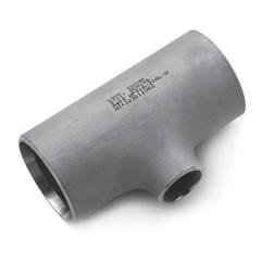
24 Tees Equal Tees ASME B16.9 MSS SP-75 O.D. O.D. N.B. at C M N.B. at C M Bevel (mm) (mm) Bevel (mm) (mm) 1/2 21, /4 26, , , , , , , , , , , , , , , , , , , , , , , , , , , , , , , , , , , , , , , , , , , , , , , , ,
 ASME B16.9 MSS SP-75 N.B. O.D.")
25 Tees Reducing Outlet Tees REDUCING OUTLET TEES (dimensions in mm) ASME B16.9 MSS SP-75 N.B. O.D. Run Outlet N.B. O.D. Run Outlet at Bevel at Bevel Run Outlet Run Outlet C M Run Outlet Run Outlet C M 1/2 3/8 21,3 17, /2 1/4 21,3 13, /4 1/2 26,7 21, /4 3/8 26,7 17, /4 33,4 26, /2 33,4 21, ,2 33, /4 42,2 26, /2 42,2 21, ,3 42, ,3 33, /4 48,3 26, /2 48,3 21, ,3 48, ,3 42, ,3 33, /4 60,3 26, ,0 60, ,0 48, ,0 42, ,0 33, ,9 73, ,9 60, ,9 48, ,9 42, ,6 88, ,6 73, ,6 60, ,6 48,
26 REDUCING OUTLET TEES (dimensions in mm) continued ASME B16.9 MSS SP-75 N.B. O.D. Run Outlet N.B. O.D. Run Outlet at Bevel at Bevel Run Outlet Run Outlet C M Run Outlet Run Outlet C M ,3 101, ,3 88, ,3 73, ,3 60, ,3 48, ,3 114, ,3 101, ,3 88, ,3 73, ,3 60, ,3 141, ,3 114, ,3 101, ,3 88, ,3 73, ,1 168, ,1 141, ,1 114, ,1 101, ,0 219, ,0 168, ,0 141, ,0 114, ,8 273, ,8 219, ,8 168, ,8 141, ,6 323, ,6 273, ,6 219, ,6 168, ,4 355, ,4 355, ,4 323, ,4 323, ,4 273, ,4 273, ,4 219, ,4 219, ,4 168, ,4 168, , , , , , , , , , , , , , , , , , , , , , , , , , , , , , , , , , , , , , , , , , , , , , , , ,
27 REDUCING OUTLET TEES (dimensions in mm) continued ASME B16.9 MSS SP-75 N.B. O.D. Run Outlet N.B. O.D. Run Outlet at Bevel at Bevel Run Outlet Run Outlet C M Run Outlet Run Outlet C M , , , , , , , , , , , , , , , , , , , , , , , , , , , , , , , , , , , , , , , , , , , , , , , , , , , , , , , , , , , , , , , , , , , , , , , , , , , , , , , , , , , , , , , , , , , , , , , , , , , , , , , , , , , , , , , , , , , , , , , , , , , , , ,
28 REDUCING OUTLET TEES (dimensions in mm) continued ASME B16.9 MSS SP-75 N.B. O.D. Run Outlet N.B. O.D. Run Outlet at Bevel at Bevel Run Outlet Run Outlet C M Run Outlet Run Outlet C M , ,

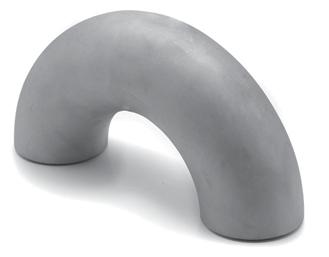
29 Long Radius Bends Long Radius Return Bends LONG RADIUS RETURN BENDS (dimensions in mm) ASME B16.9 O.D. N.B. at O K Bevel 1/2 21, /4 26, , , , , , , , , , , , , , , , , , , ,
 ASME B16.9 MSS SP-75 O.D. O.D. N.B. at Bevel N.B. at Bevel L.E. S.E. L.E. S.E. H L.E. S.E. L.E. S.E. H ASME B16.9 MSS SP-75 O.D. O.D. N.B. at Bevel N.B. at Bevel L.E. S.E.")
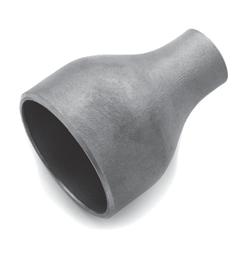
30 Reducers Concentric and eccentric reducers REDUCERS (dimensions in mm) ASME B16.9 MSS SP-75 O.D. O.D. N.B. at Bevel N.B. at Bevel L.E. S.E. L.E. S.E. H L.E. S.E. L.E. S.E. H ASME B16.9 MSS SP-75 O.D. O.D. N.B. at Bevel N.B. at Bevel L.E. S.E. L.E. S.E. H L.E. S.E. L.E. S.E. H 3/4 3/8 26,7 17,3 38 3/4 1/2 26,7 21, /4 33,4 26, /2 33,4 21, ,2 33, /4 42,2 26, /2 42,2 21, ,3 42, ,3 33, /4 48,3 26, /2 48,3 21, ,3 48, ,3 42, ,3 33, /4 60,3 26, ,0 60, ,0 48, ,0 42, ,0 33, ,9 73, ,9 60, ,9 48, ,9 42, ,6 88, ,6 73, ,6 60, ,6 48, ,6 42, ,3 101, ,3 88, ,3 73, ,3 60, ,3 48,3 102 NOTE: LE = Large End SE = Small End ,3 114, ,3 101, ,3 88, ,3 73, ,3 60, ,3 141, ,3 114, ,3 101, ,3 88, ,3 73, ,1 168, ,1 141, ,1 114, ,1 101, ,0 219, ,0 168, ,0 141, ,0 114, ,8 273, ,8 219, ,8 168, ,8 141, ,6 323, ,6 273, ,6 219, ,6 168, ,4 355, ,4 355, ,4 323, ,4 323, ,4 273, ,4 273, ,4 219, ,4 219, ,2 406, ,2 406, ,0 355, ,0 355, ,0 323, ,0 323, ,0 273, ,0 273,0 381
31 REDUCERS (dimensions in mm) - continued ASME B16.9 MSS SP-75 O.D. O.D. N.B. at Bevel N.B. at Bevel L.E. S.E. L.E. S.E. H L.E. S.E. L.E. S.E. H ASME B16.9 MSS SP-75 O.D. O.D. N.B. at Bevel N.B. at Bevel L.E. S.E. L.E. S.E. H L.E. S.E. L.E. S.E. H , , , , , , , , , , , , NOTE: LE = Large End SE = Small End


32 Stub Ends Lap-Joint Stub Ends LAP-JOINT STUB ENDS (dimensions in mm) ASME B long type O.D. RAD. DIA. O.D. of N.B. at F of of Barrel Bevel Fillet Lap R G Max. Min. 1/2 21, ,8 20,5 3/4 26, ,1 25,9 1 33, ,0 32, , ,6 41, , ,9 47,5 2 60, ,4 59, , ,3 72,2 3 88, ,3 88, , ,0 100, , ,7 113, , ,3 140, , ,3 167, , ,1 218, , ,2 272, , ,0 323, , ,9 354, , ,0 405, , ,0 456, , ,0 507, , ,0 558, , ,0 609,0 ASME B Short type / MSS SP 43 Type A O.D. RAD. DIA. O.D. of N.B. at F of of Barrel Bevel Fillet Lap R G Max. Min. 1/2 21, ,8 20,5 3/4 26, ,1 25,9 1 33, ,0 32, , ,6 41, , ,9 47,5 2 60, ,4 59, , ,3 72,2 3 88, ,3 88, , ,0 100, , ,7 113, , ,3 140, , ,3 167, , ,1 218, , ,2 272, , ,0 323, , ,9 354, , ,0 405, , ,0 456, , ,0 507, , ,0 558, , ,0 609,0 When used with the higher pressure flanges, it may be necessary to increase the length of stub ends in sizes 12in and larger. Such increase in length shall be a matter of agreement between the manufacturer and purchaser. R These dimensions conform to the radius established for lap-joint flanges in American National Standard Steel Pipe Flanges and Flanged Fittings ANSI B16.5. G The dimension conform to standard machined facings shown in the Americam National Standard Steel Pipe Flanges and Flanged Fittings ANSI B16.5. The back face of the lap shall be machined to conform to the surface on which it seats. Where ring joint facings are to be applied use dimension K as given in ANSI B16.5. F When special facings such as tongoue-groove, male-female, etc. are employed, additional lap thickness must be provided and such additional thickness shall be in addition to (not included in) the basic length F.

33 End Caps END CAPS (dimensions in mm) ASME B16.9 MSS SP-75 # Limiting 3 # Limiting O.D. at W.T. O.D. at W.T. N.B. Bevel E for E 1 N.B. Bevel E for E 1 Length E Length E 1/2 21,3 25 4, /4 26,7 25 3, ,4 38 4, ,2 38 4, ,3 38 5, ,3 38 5, ,0 38 7, ,9 51 7, ,6 64 8, ,3 64 8, ,3 76 9, , , , , , , , , , , , , , , , , , , , , , , , , , , , , , , , , , ,4 381 *The shape of these caps shall be ellipsoidal and shall conform to the shape requirements as given in ASME Boiler and Pressure Vessel Code. #Length E applies for thickness not exceeding that given in column Limiting Wall Thickness for Length E. *3 Length E1, applies for thickness greater than that given in column Limiting Wall Thickness for sizes 24in. and smaller. For type B16.9 sizes 26in. and larger the length E1, shall be by agreement between manufacturer and purchaser. 3
![Short radius elbows ASME B16.28 [mm] O.D. at Bevel - D Center to End dim. - A N.B. (inch) Min. Nom. Max.](/docs-images/99/141077620/images/34-0.jpg "Min. Nom. Max.")

34 Short radius elbows ASME B16.28 [mm] O.D. at Bevel - D Center to End dim. - A N.B. (inch) Min. Nom. Max. Min. Nom. Max Short radius 180 returns ASME B16.28 [mm] O.D. at Center to Back to N.B. Bevel - D Center - O Bevel Face - K (inch) Min. Nom. Max. Min. Nom. Max. Min. Nom. Max
35 Bevel types Welding Bevel For Fittings MSS SP 75 (mm) 10 0 ± 1 0 * Rad. t 20 v 37,5 0 ± 2,5 0 *t=20 max. 20 1,6±0,8 1,6±0,8 *NOTE: Plain bevel up to t 25,4 mm at manufacturers option. Plain bevel may be 37,5 o up to 24 at manufacturers option. Welding Bevel For Fittings ANSI B16.9/B16.28 (mm) 10 0 ± ,5 0 ± 2,5 0 Rad. t 22,2 v 37,5 0 ± 2,5 0 t max 22,2 20 1,6±0,8 1,6±0,8
36 Tolerances TOLERANCE (mm) FOR MSS SP 75 All Fittings Nominal Inside Wall Out-of-roundness Center-to-end Overall Overall Angularity Elbows Reducers Pipe Diameter Thick- Dimensions Length Length Off Angle Off Plane Off Plane Size at End ness A, B, C, M H E Q P P At ends of fittings Throughout Body of Tees & Elbows Other Elbows 1.5R elbows 3R elbows Reducers Caps 16 to 24 ± % ± 2.3 ± 3.1 ± 2.3 ± % 26 to 36 ± Note % ± 3.1 ± 6.4 ± 4.8 ± % 38 to 48 ± Note % ± 4.8 ± 9.7 ± 9.7 ± % NOTE: 1) The inside diameter at end shall be determined by circumferential measurements, and the tolerace refers to variations from nominal I.D. calculations by (OD nom - 2t nom). 2) Out-of-roundness tolerances shall be the difference between the maximum and minimum diameters measured on any radial cross-section. 3) Minus 0.3 mm except that isolated non-continuous reduction are permitted in accordance with subsection Excess thickness whether on inside or outside is to be treated in accordance with sketch given in Figure 3. 4) When elbows are intended for field segmenting, out-of-roundness tolerance may be furnished to 1% by agreement between the manufacturer and the purchaser. It is recognized that extra thickness, if any, may be on the I.D. 5) Out-of-roundness toleraces at ends shall be 1% of diameter for NPS 26 and larger. 6) Percent of O.D. NOTE: Outside diameter may be tapered at angle to 30 o beyond weld bevel.
37 TOLERANCES - ASME B16.9/B Deg Reducers and and 45-Deg Lap- All Fittings Elbows Joint Caps 180-Deg Returns Lap-Joint Ends and Stub Tees Ends Nominal Outside* Inside Wall Centre-to Overall Overall Centre-to- Back-to-Face Alignment Outside Fillet Pipe Diameter Diameter Thick- End Length Length Centre Dimension of Ends Diameter Radius Size at Bevel at End ness Dimension Dimension of Lap of Lap (inch) (1), (2) (1), (3), (4) (3) A, B, C, M F, H E O K U G R / ±0.8 ±2 ±2 ±3 ±6 ±6 ± /2 ±1.6 ±1.6 Not ±2 ±2 ±3 ±6 ±6 ± less than ±1.6 ± % ±2 ±2 ±3 ±6 ±6 ± of +2.4 nominal ±1.6 thick- ±2 ±2 ±6 ±6 ±6 ± ness ±3.2 ±2 ±2 ±6 ±10 ±6 ± ±4.8 ±2 ±2 ±6 ±10 ±6 ± ±4.8 ±3 ±5 ± ±4.8 ±5 ±5 ± NOTE: 1) Out-of-round is the sum of absolute values of plus and minus tolerance. 2) This tolerance may be exceeded in localized areas of formed fittings where increased wall thicknss is required to meet design requirements of para ) The inside diameter and the nominal wall thichknesses at ends are to be specified by the purchaser. 4) Unless otherwise specified by the purchaser, these tolerances apply to the nominal inside diameter, which equals the difference between the nominal outside and twice the nominal wall thickness. Angularity Tol. Nominal Pipe Off Off Size Angle Plane (inch) Q (mm) P (mm) 1/

38
39 SME


40 SME
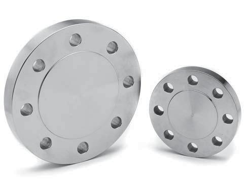
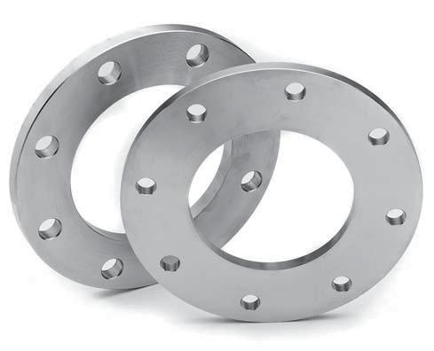
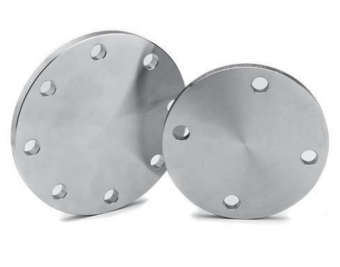
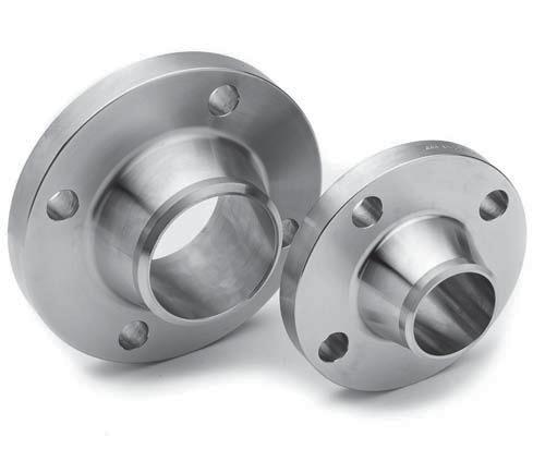
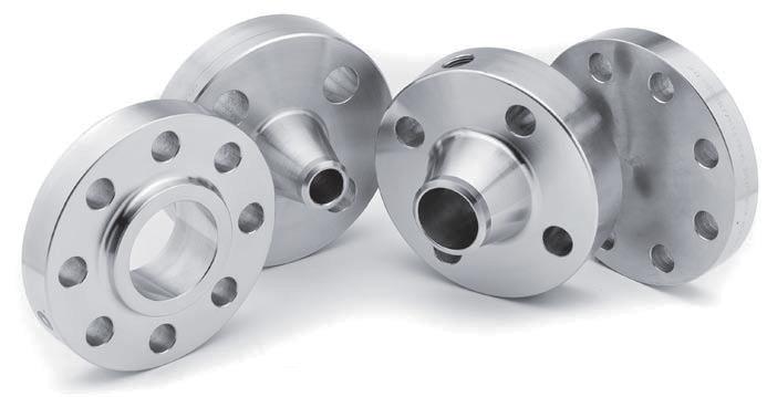
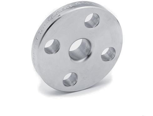
41 SME CLASS 150 FLANGES DIMENSIONS OF CLASS 150 FLANGES (mm) Flange dimensions HUB dimensions Length Through HUB Threaded flange SW Bore Nominal Thr. Pipe OD Large Small Slip, Weld Counter Thread Socket Slip-On, Weld Size flange Thickn. end end Sw Lapped neck bore length depth SW Lapped neck NPS O tf min. # X A Y Y Y Q min. T min. D B min. B min. B 1/2 90,0 9,6 30,0 21,3 14,0 16,0 46, ,0 10,0 22,2 22,9 15,8 3/4 100,0 11,2 38,0 26,7 14,0 16,0 51, ,0 11,0 27,7 28,2 20, ,0 12,7 49,0 33,4 16,0 17,0 54, ,0 13,0 34,5 34,9 26, ,0 14,3 59,0 42,2 19,0 21,0 56, ,0 14,0 43,2 43,7 35, ,0 15,9 65,0 48,3 21,0 22,0 60, ,0 16,0 49,5 50,0 40, ,0 17,5 78,0 60,3 24,0 25,0 62, ,0 17,0 61,9 62,5 52, ,0 20,7 90,0 73,0 27,0 29,0 68, ,0 19,0 74,6 75,4 62, ,0 22,3 108,0 88,9 29,0 30,0 68, ,0 21,0 90,7 91,4 77, ,0 22,3 122,0 101,6 30,0 32,0 70, , ,4 104,1 90, ,0 22,3 135,0 114,3 32,0 33,0 75, , ,1 116,8 102, ,0 22,3 164,0 141,3 35,0 36,0 87, , ,8 144,4 128, ,0 23,9 192,0 168,3 38,0 40,0 87, , ,7 171,4 154, ,0 27,0 246,0 219,1 43,0 44,0 100, , ,5 222,2 202, ,0 28,6 305,0 273,0 48,0 49,0 100, , ,2 277,4 254, ,0 30,2 365,0 323,8 54,0 56,0 113, , ,0 328,2 304, ,0 33,4 400,0 355,6 56,0 79,0 125, , ,2 360,2 To be ,0 35,0 457,0 406,4 62,0 87,0 125, , ,5 411,2 specified ,0 38,1 505,0 457,0 67,0 97,0 138, , ,8 462,3 by ,0 41,3 559,0 508,0 71,0 103,0 143, , ,1 514,4 purchaser ,0 46,1 663,0 610,0 81,0 111,0 151, , ,0 616,0 NOTE: All dimensions except NPS and bolt diameter are in millimeters. The dimensions B 2 for SW flange equals B for Weld Neck. (1) the tolerance for E is only applicable for groove depth # Lapped flange shall be 1.6 mm thicker than table value.
42 ASME CLASS 150 FLANGES K min. P O W R DIMENSIONS OF CLASS 150 FLANGES (mm) Nominal RF dimensions RTJ dimensions Bolt hole drilling Stud bolt length Pipe Groove Groove Groove Groove Bolt Bolt No of Bolt 2,0mm Ring Size OD Height OD Height number Pitch Depth Width Circle hole bolts diam. RF Joint NPS R K E P E F W Bh L L 1/2 34,9 2, ,3 15,9 4 1/2 55,0... 3/4 42,9 2, ,9 15,9 4 1/2 65, ,8 2,0 63,5 6,35 R15 47,63 6,35 8,74 79,4 15,9 4 1/2 65,0 75, ,5 2,0 73,0 6,35 R17 57,15 6,35 8,74 88,9 15,9 4 1/2 70,0 85, ,0 2,0 82,5 6,35 R19 65,07 6,35 8,74 98,4 15,9 4 1/2 70,0 85,0 2 92,1 2,0 102,0 6,35 R22 82,55 6,35 8,74 120,7 19,1 4 5/8 85,0 95, ,8 2,0 121,0 6,35 R25 101,60 6,35 8,74 139,7 19,1 4 5/8 90,0 100, ,0 2,0 133,0 6,35 R29 114,30 6,35 8,74 152,4 19,1 4 5/8 90,0 100, ,7 2,0 154,0 6,35 R33 131,78 6,35 8,74 177,8 19,1 8 5/8 90,0 100, ,2 2,0 171,0 6,35 R36 149,23 6,35 8,74 190,5 19,1 8 5/8 90,0 100, ,7 2,0 194,0 6,35 R40 171,45 6,35 8,74 215,9 22,2 8 3/4 95,0 110, ,9 2,0 219,0 6,35 R43 193,68 6,35 8,74 241,3 22,2 8 3/4 100,0 115, ,9 2,0 273,0 6,35 R48 247,65 6,35 8,74 298,5 22,2 8 3/4 110,0 120, ,8 2,0 330,0 6,35 R52 304,80 6,35 8,74 362,0 25,4 12 7/8 115,0 125, ,0 2,0 406,0 6,35 R56 381,00 6,35 8,74 431,8 25,4 12 7/8 120,0 135, ,8 2,0 425,0 6,35 R59 396,88 6,35 8,74 476,3 28, ,0 145, ,9 2,0 483,0 6,35 R64 454,03 6,35 8,74 539,8 28, ,0 145, ,4 2,0 546,0 6,35 R68 517,53 6,35 8,74 577,9 31, ,0 160, ,2 2,0 597,0 6,35 R72 558,80 6,35 8,74 635,0 31, ,0 170, ,2 2,0 711,0 6,35 R76 673,10 6,35 8,74 749,3 34, ,0 185,0 NOTE: All dimensions except NPS and bolt diameter are in millimeters. The dimensions B 2 for SW flange equals B for Weld Neck. (1) the tolerance for E is only applicable for groove depth
43 SME CLASS 300 FLANGES DIMENSIONS OF CLASS 300 FLANGES (mm) Flange dimensions HUB dimensions Length Through HUB Threaded flange SW Bore Nominal Thr. Pipe OD Large Small Slip, Weld Counter Thread Socket Slip-On, Weld Size flange Thickn. end end Sw. Lapped neck bore length depth SW Lapped neck NPS O tf min. # X A Y Y Y Q min. T min. D B min. B min. B 1/2 95,0 12,7 38,0 21,3 21,0 22,0 51,0 23,6 16,0 10,0 22,2 22,9 15,8 3/4 115,0 14,3 48,0 26,7 24,0 25,0 56,0 29,0 16,0 11,0 27,7 28,2 20, ,0 15,9 54,0 33,4 25,0 27,0 60,0 35,8 18,0 13,0 34,5 34,9 26, ,0 17,5 64,0 42,2 25,0 27,0 64,0 44,4 21,0 14,0 43,2 43,7 35, ,0 19,1 70,0 48,3 29,0 30,0 67,0 50,3 23,0 16,0 49,5 50,0 40, ,0 20,7 84,0 60,3 32,0 33,0 68,0 63,5 29,0 17,0 61,9 62,5 52, ,0 23,9 100,0 73,0 37,0 38,0 75,0 76,2 32,0 19,0 74,6 75,4 62, ,0 27,0 117,0 88,9 41,0 43,0 78,0 92,2 32,0 21,0 90,7 91,4 77, ,0 28,6 133,0 101,6 43,0 44,0 79,0 104,9 37, ,4 104,1 90, ,0 30,2 146,0 114,3 46,0 48,0 84,0 117,6 37, ,1 116,8 102, ,0 33,4 178,0 141,3 49,0 51,0 97,0 144,4 43, ,8 144,4 128, ,0 35,0 206,0 168,3 51,0 52,0 97,0 171,4 47, ,7 171,4 154, ,0 39,7 260,0 219,1 60,0 62,0 110,0 222,2 51, ,5 222,2 202, ,0 46,1 321,0 273,0 65,0 95,0 116,0 276,2 56, ,2 277,4 254, ,0 49,3 375,0 323,8 71,0 102,0 129,0 328,6 61, ,0 328,2 304, ,0 650,0 710,0 775,0 52,4 55,6 58,8 62,0 425,0 483,0 533,0 587,0 355,6 406,4 457,0 508,0 75,0 81,0 87,0 94,0 111,0 121,0 130,0 140,0 141,0 144,0 157,0 160,0 360,4 411,2 462,0 512,8 64,0 69,0 70,0 74, ,2 410,5 461,8 513,1 360,2 411,2 462,3 514,4 To be specified by purchaser ,0 68,3 702,0 610,0 105,0 152,0 167,0 614,4 83, ,0 616,0 NOTE: All dimensions except NPS and bolt diameter are in millimeters. The dimensions B 2 for SW flange equals B for Weld Neck. (1) the tolerance for E is only applicable for groove depth # Lapped flange shall be 1.6 mm thicker than table value.
44 ASME CLASS 300 FLANGES K min. P O W R DIMENSIONS OF CLASS 300 FLANGES (mm) RF dimensions RTJ dimensions Bolt hole drilling Stud bolt length Nominal Pipe Groove Groove Groove Groove Bolt Bolt No of Bolt 2,0mm Ring Size OD Height OD Height number Pitch Depth Width Circle hole bolts diam. RF Joint NPS R K E P E F W Bh L L 1/2 34,9 2,0 51,0 5,54 R11 34,14 5,54 7,14 66,7 15,9 4 1/2 65,0 75,0 3/4 42,9 2,0 63,5 6,35 R13 42,88 6,35 8,74 82,6 19,1 4 5/8 75,0 90,0 1 50,8 2,0 70,0 6,35 R16 50,80 6,35 8,74 88,9 19,1 4 5/8 75,0 90, ,5 2,0 79,5 6,35 R18 60,33 6,35 8,74 98,4 19,1 4 5/8 85,0 95, ,0 2,0 90,5 6,35 R20 68,27 6,35 8,74 114,3 22,2 4 3/4 90,0 100,0 2 92,1 2,0 108,0 7,92 R23 82,55 7,92 11,91 127,0 19,1 8 5/8 90,0 100, ,8 2,0 127,0 7,92 R26 101,60 7,92 11,91 149,2 22,2 8 3/4 100,0 115, ,0 2,0 146,0 7,92 R31 123,83 7,92 11,91 168,3 22,2 8 3/4 110,0 120, ,7 2,0 159,0 7,92 R34 131,78 7,92 11,91 184,2 22,2 8 3/4 110,0 125, ,2 2,0 175,0 7,92 R37 149,23 7,92 11,91 200,0 22,2 8 3/4 115,0 125, ,7 2,0 210,0 7,92 R41 180,98 7,92 11,91 235,0 22,2 8 3/4 120,0 135, ,9 2,0 241,0 7,92 R45 211,12 7,92 11,91 269,9 22,2 12 3/4 120,0 140, ,9 2,0 302,0 7,92 R49 269,88 7,92 11,91 330,2 25,4 12 7/8 140,0 150, ,8 2,0 356,0 7,92 R53 323,85 7,92 11,91 387,4 28, ,0 170, ,0 2,0 413,0 7,92 R57 381,00 7,92 11,91 450,8 31, ,0 185, ,8 2,0 457,0 7,92 R61 419,10 7,92 11,91 514,4 31, ,0 190, ,9 2,0 508,0 7,92 R65 469,90 7,92 11,91 571,5 34, ,0 205, ,4 2,0 575,0 7,92 R69 533,40 7,92 11,91 628,6 34, ,0 210, ,2 2,0 635,0 9,53 R73 584,20 9,53 13,49 685,8 34, ,0 220, ,2 2,0 749,0 11,13 R77 692,15 11,13 16,66 812,8 41, ,0 255,0 NOTE: All dimensions except NPS and bolt diameter are in millimeters. The dimensions B 2 for SW flange equals B for Weld Neck. (1) the tolerance for E is only applicable for groove depth
45 SME CLASS 400 FLANGES DIMENSIONS OF CLASS 400 FLANGES (mm) Flange dimensions HUB dimensions Length Through HUB Threaded flange SW Bore Nominal Pipe OD Large Small Thr. Weld Counter Thread Socket Slip-On, Weld Size flange Thickn. end end Slip. Lapped neck bore length depth Lapped neck NPS O tf min. X A Y Y Y Q min. T min. D B min. B min. B 1/2 3/ Use Class 600 dimensions in these sizes ,0 35,0 146,0 114,3 51,0 51,0 89,0 117,6 37, ,1 116, ,0 38,1 178,0 141,3 54,0 54,0 102,0 144,4 43, ,8 144, ,0 41,3 206,0 168,3 57,0 57,0 103,0 171,4 46, ,7 171, ,0 47,7 260,0 219,1 68,0 68,0 117,0 222,2 51, ,5 222, ,0 54,0 321,0 273,0 73,0 102,0 124,0 276,2 56, ,2 277, ,0 57,2 375,0 323,8 79,0 108,0 137,0 328,6 61, ,0 328, ,0 60,4 425,0 355,6 84,0 117,0 149,0 360,4 64, ,2 360, ,0 63,5 483,0 406,4 94,0 127,0 152,0 411,2 69, ,5 411, ,0 66,7 533,0 457,0 98,0 137,0 165,0 462,0 70, ,8 462, ,0 69,9 587,0 508,0 102,0 146,0 168,0 512,8 74, ,1 514, ,0 76,2 702,0 610,0 114,0 159,0 175,0 614,4 83, ,0 616,0 To be specified by purchaser NOTE: All dimensions except NPS and bolt diameter are in millimeters. (1) the tolerance for E is only applicable for groove depth
46 ASME CLASS 400 FLANGES K min. P O W R DIMENSIONS OF CLASS 400 FLANGES (mm) Nominal RF dimensions RTJ dimensions Bolt hole drilling Stud bolt length Pipe Groove Groove Groove Groove Bolt Bolt No of Bolt 7,0 mm Ring Size OD Height OD Height number Pitch Depth Width Circle hole RF diam. RF Joint NPS R K E P E F W Bh L L 1/2 3/ Use Class 600 dimensions in these sizes ,2 7,0 175,0 7,92 R37 149,23 7,92 11,91 200,0 25,4 8 7/8 140,0 140, ,7 7,0 210,0 7,92 R41 180,98 7,92 11,91 235,0 25,4 8 7/8 145,0 145, ,9 7,0 241,0 7,92 R45 211,12 7,92 11,91 269,9 25,4 12 7/8 150,0 150, ,9 7,0 302,0 7,92 R49 269,88 7,92 11,91 330,0 28, ,0 170, ,8 7,0 356,0 7,92 R53 323,85 7,92 11,91 387,4 31, ,0 190, ,0 7,0 413,0 7,92 R57 381,00 7,92 11,91 450,8 34, ,0 205, ,8 7,0 457,0 7,92 R61 419,10 7,92 11,91 514,4 34, ,0 210, ,9 7,0 508,0 7,92 R65 469,90 7,92 11,91 571,5 38, ,0 220, ,4 7,0 575,0 7,92 R69 533,40 7,92 11,91 628,6 38, ,0 230, ,2 7,0 635,0 9,53 R73 584,20 9,53 13,49 685,8 41, ,0 250, ,2 7,0 749,0 11,13 R77 692,15 11,13 16,66 812,8 47, ,0 280,0 NOTE: All dimensions except NPS and bolt diameter are in millimeters. (1) the tolerance for E is only applicable for groove depth
47 SME CLASS 600 FLANGES DIMENSIONS OF CLASS 600 FLANGES (mm) Flange dimensions HUB dimensions Length Through HUB Threaded flange SW Bore Nominal Thr. Pipe OD Large Small Slip. Weld Counter Thread Socket Slip-On, Weld Size flange Thickn. end end SW Lapped neck bore length depth SW Lapped neck NPS O tf min. X A Y Y Y Q min. T min. D B min. B min. B 1/2 95,0 14,3 38,0 21,3 22,0 22,0 52,0 23,6 16,0 10,0 22,2 22,9 3/4 115,0 15,9 48,0 26,7 25,0 25,0 57,0 29,0 16,0 11,0 27,7 28, ,0 17,5 54,0 33,4 27,0 27,0 62,0 35,8 18,0 13,0 34,5 34, ,0 20,7 64,0 42,2 29,0 29,0 67,0 44,4 21,0 14,0 43,2 43, ,0 22,3 70,0 48,3 32,0 32,0 70,0 50,6 23,0 16,0 49,5 50, ,0 25,4 84,0 60,3 37,0 37,0 73,0 63,5 29,0 17,0 61,9 62, ,0 28,6 100,0 73,0 41,0 41,0 79,0 76,2 32,0 19,0 74,6 75, ,0 31,8 117,0 88,9 46,0 46,0 83,0 92,2 35,0 21,0 90,7 91, ,0 35,0 133,0 101,6 49,0 49,0 86,0 104,9 40,0,,, 103,4 104, ,0 38,1 152,0 114,3 54,0 54,0 102,0 117,6 42,0,,, 116,1 116, ,0 44,5 189,0 141,3 60,0 60,0 114,0 144,4 48,0,,, 143,8 144, ,0 47,7 222,0 168,3 67,0 67,0 117,0 171,4 51,0,,, 170,7 171, ,0 55,6 273,0 219,1 76,0 76,0 133,0 222,2 58,0,,, 221,5 222, ,0 63,5 343,0 273,0 86,0 111,0 152,0 276,2 66,0,,, 276,2 277, ,0 66,7 400,0 323,8 92,0 117,0 156,0 328,6 70,0,,, 327,0 328, ,0 69,9 432,0 355,6 94,0 127,0 165,0 360,4 74,0,,, 359,2 360, ,0 76,2 495,0 406,4 106,0 140,0 178,0 411,2 78,0,,, 410,5 411, ,0 82,6 546,0 457,0 117,0 152,0 184,0 462,0 80,0,,, 461,8 462, ,0 88,9 610,0 508,0 127,0 165,0 190,0 512,8 83,0,,, 513,1 514, ,0 101,6 718,0 610,0 140,0 184,0 203,0 614,4 93,0,,, 616,0 616,0 To be specified by purchaser NOTE: All dimensions except NPS and bolt diameter are in millimeters. The dimensions B 2 for SW flange equals B for Weld Neck. (1) the tolerance for E is only applicable for groove depth
48 ASME CLASS 600 FLANGES K min. P O W R DIMENSIONS OF CLASS 600 FLANGES (mm) RF dimensions RTJ dimensions Bolt hole drilling Stud bolt length Nominal Pipe Groove Groove Groove Groove Bolt Bolt No of Bolt 7.0 mm Ring Size OD Height OD Height number Pitch Depth Width Circle hole bolts diam. RF Joint NPS R K E P E F W Bh L L 1/2 34,9 7,0 51,0 5,54 R11 34,14 5,54 7,14 66,7 15,9 4 1/2 75,0 75,0 3/4 42,9 7,0 63,5 6,35 R13 42,88 6,35 8,74 82,6 19,1 4 5/8 90,0 90,0 1 50,8 7,0 70,0 6,35 R16 50,80 6,35 8,74 88,9 19,1 4 5/8 90,0 90, ,5 7,0 79,5 6,35 R18 60,33 6,35 8,74 98,4 19,1 4 5/8 95,0 95, ,0 7,0 90,5 6,35 R20 68,27 6,35 8,74 114,3 22,2 4 3/4 110,0 110,0 2 92,1 7,0 108,0 7,92 R23 82,55 7,92 11,91 127,0 19,1 8 5/8 110,0 110, ,8 7,0 127,0 7,92 R26 101,60 7,92 11,91 149,2 22,2 8 3/4 120,0 120, ,0 7,0 146,0 7,92 R31 123,83 7,92 11,91 168,3 22,2 8 3/4 125,0 125, ,7 7,0 159,0 7,92 R34 131,78 7,92 11,91 184,2 25,4 8 7/8 140,0 140, ,2 7,0 175,0 7,92 R37 149,23 7,92 11,91 215,9 25,4 8 7/8 145,0 145, ,7 7,0 210,0 7,92 R41 180,98 7,92 11,91 266,7 28, ,0 165, ,9 7,0 241,0 7,92 R45 211,12 7,92 11,91 292,1 28, ,0 170, ,9 7,0 302,0 7,92 R49 269,88 7,92 11,91 349,2 31, ,0 195, ,8 7,0 356,0 7,92 R53 323,85 7,92 11,91 431,8 34, ,0 215, ,0 7,0 413,0 7,92 R57 381,00 7,92 11,91 489,0 34, ,0 220, ,8 7,0 457,0 7,92 R61 419,10 7,92 11,91 527,0 38, ,0 235, ,9 7,0 508,0 7,92 R65 469,90 7,92 11,91 603,2 41, ,0 255, ,4 7,0 575,0 7,92 R69 533,40 7,92 11,91 654,0 44, ,0 275, ,2 7,0 635,0 9,53 R73 584,20 9,53 13,49 723,9 44, ,0 290, ,2 7,0 749,0 11,13 R77 692,15 11,13 16,66 838,2 50, ,0 335,0 NOTE: All dimensions except NPS and bolt diameter are in millimeters. The dimensions B for SW flange equals B for Weld Neck. (1) the tolerance for E is only applicable for groove depth
49 SME CLASS 900 FLANGES DIMENSIONS OF CLASS 900 FLANGES (mm) Flange dimensions HUB dimensions Length Through HUB Threaded flange SW Bore Nominal Pipe OD Large Small Thr. Weld Counter Thread Socket Slip-On Weld Size flange Thickn. end end Slip. Lapped neck bore length depth Lapped neck NPS O tf min. X A Y Y Y Q min. T min. D B min. B min. B 1/2 3/ Use Class 1500 dimensions in these sizes ,0 38,1 127,0 88,9 54,0 54,0 102,0 92,2 42, ,7 91, ,0 44,5 159,0 114,3 70,0 70,0 114,0 117,6 48, ,1 116, ,0 50,8 190,0 141,3 79,0 79,0 127,0 144,4 54, ,8 144, ,0 55,6 235,0 168,3 86,0 86,0 140,0 171,4 58, ,7 171, ,0 63,5 298,0 219,1 102,0 114,0 162,0 222,2 64, ,5 222, ,0 69,9 368,0 273,0 108,0 127,0 184,0 276,2 72, ,2 277, ,0 79,4 419,0 323,8 117,0 143,0 200,0 328,6 77, ,0 328, ,0 85,8 451,0 355,6 130,0 156,0 213,0 360,4 83, ,2 360, ,0 88,9 508,0 406,4 133,0 165,0 216,0 411,2 86, ,5 411, ,0 101,6 565,0 457,0 152,0 190,0 229,0 462,0 89, ,8 462, ,0 108,0 622,0 508,0 159,0 210,0 248,0 512,8 93, ,1 514, ,0 139,7 749,0 610,0 203,0 267,0 292,0 614,4 102, ,0 616,0 To be specified by purchaser NOTE: All dimensions except NPS and bolt diameter are in millimeters. (1) the tolerance for E is only applicable for groove depth
50 ASME CLASS 900 FLANGES K min. P O W R DIMENSIONS OF CLASS 900 FLANGES (mm) RF dimensions RTJ dimensions Bolt hole drilling Stud bolt length Nominal Pipe Groove Groove Groove Groove Bolt Bolt No of Bolt 7,0 mm Ring Size OD Height OD Height number Pitch Depth Width Circle hole bolts diam. RF Joint NPS R K E P E F W Bh L L 1/2 3/ Use Class 1500 dimensions in these sizes ,0 7,0 156,0 7,92 R31 123,83 7,92 11,91 190,5 25,4 8 7/8 145,0 145, ,2 7,0 181,0 7,92 R37 149,23 7,92 11,91 235,0 31, ,0 170, ,7 7,0 216,0 7,92 R41 180,98 7,92 11,91 279,4 34, ,0 190, ,9 7,0 241,0 7,92 R45 211,12 7,92 11,91 317,5 31, ,0 195, ,9 7,0 308,0 7,92 R49 269,88 7,92 11,91 393,7 38, ,0 220, ,8 7,0 362,0 7,92 R53 323,85 7,92 11,91 469,9 38, ,0 235, ,0 7,0 419,0 7,92 R57 381,00 7,92 11,91 533,4 38, ,0 255, ,8 7,0 467,0 11,13 R62 419,10 11,13 16,66 558,8 41, ,0 280, ,9 7,0 524,0 11,13 R66 469,90 11,13 16,66 616,0 44, ,0 290, ,4 7,0 594,0 12,70 R70 533,40 12,70 19,84 685,8 50, ,0 335, ,2 7,0 648,0 12,70 R74 584,20 12,70 19,84 749,3 54, ,0 360, ,2 7,0 772,0 15,88 R78 692,15 15,88 26,97 901,7 66, ,0 455,0 NOTE: All dimensions except NPS and bolt diameter are in millimeters. (1) the tolerance for E is only applicable for groove depth
51 SME CLASS 1500 FLANGES DIMENSIONS OF CLASS 1500 FLANGES (mm) Flange dimensions HUB dimensions Length Through HUB Threaded flange SW Bore Nominal Thr. Pipe OD Large Small Slip, Weld Counter Thread Socket Slip-On, Weld Size fla nge Thickn. end end Sw. Lapped neck bore length depth SW Lapped neck NPS O tf min. X A Y Y Y Q min. T min. D B min. B min. B 1/2 120,0 22,3 38,0 21,3 32,0 32,0 60,0 23,6 23,0 10,0 22,2 22,9 3/4 130,0 25,4 44,0 26,7 35,0 35,0 70,0 29,0 26,0 11,0 27,7 28, ,0 28,6 52,0 33,4 41,0 41,0 73,0 35,8 29,0 13,0 34,5 34, ,0 28,6 64,0 42,2 41,0 41,0 73,0 44,4 31,0 14,0 43,2 43, ,0 31,8 70,0 48,3 44,0 44,0 83,0 50,6 32,0 16,0 49,5 50, ,0 38,1 105,0 60,3 57,0 57,0 102,0 63,5 39,0 17,0 61,9 62, ,0 41,3 124,0 73,0 64,0 64,0 105,0 76,2 48,0 19,0 74,6 75, ,0 47,7 133,0 88, ,0 117, , ,0 54,0 162,0 114, ,0 124, , ,0 73,1 197,0 141, ,0 156, , ,0 82,6 229,0 168, ,0 171, , ,0 92,1 292,0 219, ,0 213, , ,0 108,0 368,0 273, ,0 254, , ,0 123,9 451,0 323, ,0 283, , ,0 133,4 495,0 355, ,0 298, , ,0 146,1 552,0 406, ,0 311, , ,0 162,0 597,0 457, ,0 327, , ,0 177,8 641,0 508, ,0 356, , ,0 203,2 762,0 610, ,0 406, ,0 To be specified by purchaser NOTE: All dimensions except NPS and bolt diameter are in millimeters. The dimensions B 2 for SW flange equals B for Weld Neck. (1) the tolerance for E is only applicable for groove depth
52 ASME CLASS 1500 FLANGES K min. P O W R DIMENSIONS OF CLASS 1500 FLANGES (mm) Nominal RF dimensions RTJ dimensions Bolt hole drilling Stud bolt length Pipe Groove Groove Groove Groove Bolt Bolt No of Bolt 7.0 mm Ring Size OD Height OD Height number Pitch Depth Width Circle hole bolts diam. RF Joint NPS R K E P E F W Bh L L 1/2 34,9 7,0 60,5 6,35 R12 39,67 6,35 8,74 82,6 22,2 4 3/4 110,0 110,0 3/4 42,9 7,0 66,5 6,35 R14 44,45 6,35 8,74 88,9 22,2 4 3/4 115,0 115,0 1 50,8 7,0 71,5 6,35 R16 50,80 6,35 8,74 101,6 25,4 4 7/8 125,0 125, ,5 7,0 81,0 6,35 R18 60,33 6,35 8,74 111,1 25,4 4 7/8 125,0 125, ,0 7,0 92,0 6,35 R20 68,27 6,35 8,74 123,8 28, ,0 140,0 2 92,1 7,0 124,0 7,92 R24 95,25 7,92 11,91 165,1 25,4 8 7/8 145,0 145, ,8 7,0 137,0 7,92 R27 107,95 7,92 11,91 190,5 28, ,0 160, ,0 7,0 168,0 7,92 R35 136,53 7,92 11,91 203,2 31, ,0 180, ,2 7,0 194,0 7,92 R39 161,93 7,92 11,91 241,3 34, ,0 195, ,7 7,0 229,0 7,92 R44 193,68 7,92 11,91 292,1 41, ,0 250, ,9 7,0 248,0 9,53 R46 211,14 9,53 13,49 317,5 38, ,0 265, ,9 7,0 318,0 11,13 R50 269,88 11,13 16,66 393,7 44, ,0 325, ,8 7,0 371,0 11,13 R54 323,85 11,13 16,66 482,6 50, ,0 345, ,0 7,0 438,0 14,27 R58 381,00 14,27 23,01 571,5 54, ,0 385, ,8 7,0 489,0 15,88 R63 419,10 15,88 26,97 635,0 60, ,0 425, ,9 7,0 546,0 17,48 R67 469,90 17,48 30,18 704,8 66, ,0 470, ,4 7,0 613,0 17,48 R71 533,40 17,48 30,18 774,7 73, ,0 525, ,2 7,0 673,0 17,48 R75 584,20 17,48 33,32 831,8 79, ,0 565, ,2 7,0 794,0 20,62 R79 692,15 20,62 36,53 990,6 92, ,0 650,0 NOTE: All dimensions except NPS and bolt diameter are in millimeters. The dimensions B 2 for SW flange equals B for Weld Neck. (1) the tolerance for E is only applicable for groove depth
53 ASME B16.5 PIPE FLANGES CLASS 2500 FLANGES DIMENSIONS OF CLASS 2500 FLANGES (mm) Flange dimensions HUB dimensions Length Through HUB Threaded flange SW Bore Nominal Pipe OD Large Small Weld Counter Thread Socket Slip-On, Weld Size flange Thickn. end end Thr. Lapped neck bore length depth SW Lapped neck NPS O tf min. X A Y Y Y Q min. T min. D B min. B min. B 1/2 135,0 30,2 43,0 21,3 40,0 40,0 73,0 23,6 29, ,9 3/4 140,0 31,8 51,0 26,7 43,0 43,0 79,0 29,0 32, , ,0 35,0 57,0 33,4 48,0 48,0 89,0 35,8 35, , ,0 38,1 73,0 42,2 52,0 52,0 95,0 44,4 39, , ,0 44,5 79,0 48,3 60,0 60,0 111,0 50,6 45, , ,0 50,9 95,0 60,3 70,0 70,0 127,0 63,5 51, , ,0 57,2 114,0 73,0 79,0 79,0 143,0 76,2 58, , ,0 66,7 133,0 88, ,0 168, , ,0 76,2 165,0 114, ,0 190, , ,0 92,1 203,0 141, ,0 229, , ,0 108,0 235,0 168, ,0 273, , ,0 127,0 305,0 219, ,0 318, , ,0 165,1 375,0 273, ,0 419, , ,0 184,2 441,0 323, ,0 464, ,2 To be specified by purchaser NOTE: All dimensions except NPS and bolt diameter are in millimeters. (1) the tolerance for E is only applicable for groove depth
54 PIPE FLANGES ASME B16.5 CLASS 2500 FLANGES K min. P O W R DIMENSIONS OF CLASS 2500 FLANGES (mm) Nominal RF dimensions RTJ dimensions Bolt hole drilling Stud bolt length Pipe Groove Groove Groove Groove Bolt Bolt No of Bolt 7,0 mm Ring Size OD Height OD Height number Pitch Depth Width Circle hole bolts diam. RF Joint NPS R K E P E F W Bh L L 1/2 34,9 7,0 65,0 6,35 R13 42,88 6,35 8,74 88,9 22,2 4 3/4 120,0 120,0 3/4 42,9 7,0 73,0 6,35 R16 50,80 6,35 8,74 95,2 22,2 4 3/4 125,0 125,0 1 50,8 7,0 82,5 6,35 R18 60,33 6,35 8,74 108,0 25,4 4 7/8 140,0 140, ,5 7,0 102,0 7,92 R21 72,23 7,92 11,91 130,2 28, ,0 150, ,0 7,0 114,0 7,92 R23 82,55 7,92 11,91 146,0 31, ,0 170,0 2 92,1 7,0 133,0 7,92 R26 101,60 7,92 11,91 171,4 28, ,0 180, ,8 7,0 149,0 9,52 R28 111,13 9,52 13,49 196,8 31, ,0 205, ,0 7,0 168,0 9,53 R32 127,00 9,53 13,49 228,6 34, ,0 230, ,2 7,0 203,0 11,13 R38 157,18 11,13 16,66 273,0 41, ,0 260, ,7 7,0 241,0 12,70 R42 190,50 12,70 19,84 323,8 47, ,0 310, ,9 7,0 279,0 12,70 R47 228,60 12,70 19,84 368,3 54, ,0 355, ,9 7,0 340,0 14,27 R51 279,40 14,27 23,01 438,2 54, ,0 395, ,8 7,0 425,0 17,48 R55 342,90 17,48 30,18 539,8 66, ,0 510, ,0 7,0 495,0 17,48 R60 406,40 17,48 33,32 619,1 73, ,0 560,0 NOTE: All dimensions except NPS and bolt diameter are in millimeters. (1) the tolerance for E is only applicable for groove depth
55 ASME B16.5 PIPE FLANGES Tolerances B DENOMINATION DESCRIPTION SIZE RANGE TOLERANCE O Outside diameter <= 24 ± 1.6 mm flange ring 1) >= 26 ± 3.2 mm Weld neck: B Inside diameter / bore <= 10 ± 1.0 mm ± 1.5 mm >= / -1.5 mm Slip-on, lap joint, socket weld, threaded <= / -0.0 mm >= / -0.0 mm A Diameter small end <= / -1.0 mm of HUB / WN end >= / -1.0 mm X Diameter of HUB base <= 24 (dimension X) / -0.8 mm >= 26 (dimension X) / -0.8 mm W Drilling and facing Bolt circle diameter ± 1.5 mm Center to center adjacent bolt holes ± 0.8 mm Max eccentricity between bolt circle diameter and machining facing diameter: <= 2 1/2 0.8 mm >= mm Y Overall HUB length <= 4 ± 1.5 mm of WN flanges / -3.0 mm >= / -5.0 mm tf Thickness of flange ring <= / -0.0 mm >= / -0.0 mm E Groove depth Applicable for groove depth only / -0.0 mm F Groove width ± 0.2 mm P Groove pitch ± 0.13 mm K RTJ raised portion / mm R RF raised portion 2.0 mm RF height ± 1.0 mm 7.0 mm RF height ± 0.5 mm 1) These tolerances are not covered by ANSI B 16.5
56 FLANGES MSS SP-44 MSS SP-44 CLASS 150 FLANGES DIMENSIONS FOR MSS SP-44 CLASS 150 FLANGES (mm) Flange dim. Hub dimension RF dimensions RTJ dimensions Bolt hole drilling OD Large Length Groove Bolt Bolt No of Nominal OD flange Thickness end through OD Height OD number Pitch Depth Width Circle Hole bolts Pipe size O C min. X Y R K P L D Bc Bh , ,3 2, ,4 35, , ,1 2, ,6 35, , ,2 2, ,4 35, , ,4 2, ,9 41, , ,2 2, ,7 41, , ,4 2, ,8 41, , ,2 2, ,4 41, , ,0 2, ,2 41, , ,8 2, ,3 41, , ,6 2, ,4 41, , ,4 2, ,2 41, , ,9 2, ,4 41, , ,7 2, ,6 47, , ,5 2, ,7 47, , ,3 2, ,8 47, , ,8 2, ,0 47, , ,6 2, ,2 47, , ,4 2, ,0 47,8 52 NOTES: Bore (B) to be specified by purchacer OD of HUB at WN end (H) depends on material properties of flange versus joining piping - see section 5.3 of MSS SP-44.
57 MSS SP-44 FLANGES MSS SP-44 CLASS 300 FLANGES DIMENSIONS FOR MSS SP-44 CLASS 300 FLANGES (mm) Flange dimension Hub dimension RF dimensions RTJ dimensions Bolt hole drilling Thickn. Thickn. OD Large Length Groove Bolt Bolt No of Nominal OD flange WN Blind end through OD Height OD number Pitch Depth Width Circle Hole bolts Pipe size O C min. E. min X Y R K P L D Bc Bh ,8 82, ,3 2,0 810 R93 749,3 12,70 19,84 876,3 44, ,2 88, ,1 2,0 861 R94 800,1 12,70 19,84 939,8 44, ,5 93, ,2 2,0 917 R95 857,3 12,70 19,84 997,0 47, ,9 98, ,4 2,0 984 R96 914,4 14,27 23, ,1 50, ,1 103, ,2 2, R97 965,2 14,27 23, ,9 50, ,2 109, ,4 2, R ,4 14,27 23, ,4 53, ,4 106, ,7 2, ,2 41, ,8 112, ,8 2, ,7 44, ,5 117, ,6 2, ,5 44, ,3 122, ,8 2, ,6 47, ,0 127, ,6 2, ,8 50, ,8 131, ,8 2, ,6 50, ,2 138, ,9 2, ,8 53, ,9 142, ,7 2, ,6 53, ,9 150, ,8 2, ,4 60, ,4 152, ,6 2, ,2 60, ,2 157, ,8 2, ,0 60, ,0 162, ,6 2, ,8 60,5 32 NOTES: Bore (B) to be specified by purchacer OD of HUB at WN end (H) depends on material properties of flange versus joining piping - see section 5.3 of MSS SP-44.
58 FLANGES MSS SP-44 MSS SP-44 CLASS 400 FLANGES DIMENSIONS FOR MSS SP-44 CLASS 400 FLANGES (mm) Flange dimension Hub dimension RF dimensions RTJ dimensions Bolt hole drilling Thickn. Thickn. OD Large Length Groove Bolt Bolt No of Nominal OD flange WN Blind end through OD Height OD number Pitch Depth Width Circle Hole bolts Pipe size O C min. E. min X Y R K P L D Bc Bh ,9 98, ,3 7,0 810 R93 749,3 12,70 19,84 876,3 47, ,3 104, ,1 7,0 861 R94 800,1 12,70 19,84 939,8 50, ,6 111, ,2 7,0 917 R95 857,3 12,70 19,84 997,0 53, ,0 115, ,4 7,0 984 R96 914,4 14,27 23, ,1 53, ,2 122, ,2 7, R97 965,2 14,27 23, ,9 53, ,3 128, ,4 7, R ,4 14,27 23, ,4 53, ,9 123, ,0 7, ,6 47, ,2 130, ,2 7, ,8 50, ,4 133, ,0 7, ,6 50, ,7 139, ,2 7, ,7 53, ,1 146, ,3 7, ,8 53, ,4 152, ,1 7, ,4 60, ,2 158, ,1 7, ,5 60, ,0 163, ,9 7, ,3 60, ,9 171, ,0 7, ,2 66, ,7 176, ,2 7, ,0 66, ,8 181, ,0 7, ,8 60, ,8 189, ,1 7, ,6 73,2 32 NOTES: Bore (B) to be specified by purchacer OD of HUB at WN end (H) depends on material properties of flange versus joining piping - see section 5.3 of MSS SP-44.
59 MSS SP-44 FLANGES MSS SP-44 CLASS 600 FLANGES DIMENSIONS FOR MSS SP-44 CLASS 600 FLANGES (mm) Flange dimension Hub dimension RF dimensions RTJ dimensions Bolt hole drilling Thickn. Thickn. OD Large Length Groove Bolt Bolt No of Nominal OD flange WN Blind end through OD Height OD number Pitch Depth Width Circle Hole bolts Pipe size O C min. E. min X Y R K P L D Bc Bh ,0 125, ,3 7,0 810 R93 749,3 12,70 19,84 914,4 50, ,2 131, ,1 7,0 861 R94 800,1 12,70 19,84 965,2 53, ,3 139, ,2 7,0 917 R95 857,3 12,70 19, ,4 53, ,5 147, ,4 7,0 984 R96 914,4 14,27 23, ,5 60, ,7 154, ,2 7, R97 965,2 14,27 23, ,3 60, ,9 162, ,4 7, R ,4 14,27 23, ,8 66, ,4 155, ,1 7, ,0 60, ,8 162, ,2 7, ,8 60, ,3 171, ,4 7, ,7 66, ,1 177, ,6 7, ,5 66, ,4 185, ,4 7, ,6 66, ,0 195, ,5 7, ,5 73, ,9 203, ,3 7, ,0 79, ,2 209, ,1 7, ,8 79, ,6 217, ,2 7, ,0 79, ,5 225, ,0 7, ,4 85, ,3 231, ,2 7, ,2 85, ,4 242, ,4 7, ,4 92,0 28 NOTES: Bore (B) to be specified by purchacer OD of HUB at WN end (H) depends on material properties of flange versus joining piping - see section 5.3 of MSS SP-44.
60 FLANGES MSS SP-44 MSS SP-44 CLASS 900 FLANGES DIMENSIONS FOR MSS SP-44 CLASS 900 FLANGES (mm) Flange dimension Hub dimension RF dimensions RTJ dimensions Bolt hole drilling Thickn. Thickn. OD Large Length Groove Bolt Bolt No of Nominal OD flange WN Blind end through OD Height OD number Pitch Depth Width Circle Hole bolts Pipe size O C min. E. min X Y R K P L D Bc Bh ,7 160, ,3 7,0 832 R ,3 17,48 30,18 952,5 73, ,9 171, ,1 7,0 889 R ,1 17,48 33, ,4 79, ,3 182, ,2 7,0 946 R ,3 17,48 33, ,8 79, ,8 193, ,4 7, R ,4 17,48 33, ,7 85, ,1 204, ,2 7, R ,2 20,62 36, ,6 92, ,5 214, ,4 7, R ,4 20,62 36, ,0 92, ,5 215, ,6 7, ,0 92, ,9 223, ,8 7, ,8 92, ,4 231, ,8 7, ,6 92, ,4 242, ,0 7, ,7 98, ,5 255, ,5 7, ,7 104, ,4 263, ,3 7, ,5 104,7 24 NOTES: Bore (B) to be specified by purchacer OD of HUB at WN end (H) depends on material properties of flange versus joining piping - see section 5.3 of MSS SP-44.
61 MSS SP-44 FLANGES TOLERANCES MSS SP Denomination Description Size range Tolerance O Outside diameter (>= 26 ) ±3.2 mm flange ring - note 1 B Inside diameter / (>=20 ) / -1.5 mm bore H Diameter small end (>= 26 ) / -1.5 mm of HUB / WN end X Diameter of HUB base - (>= 26 dimension X) / -0.8 mm note 1 Drilling and facing Bolt circle diameter ±1.5 mm Center to center adjacent bolt holes ±0.8 mm Max eccentricity between bolt circle diam. and machining facing diameter 2.0 mm Y Overall HUB length (>= 26 ) ±5.0 mm C or E Thickness of (>=20 ) / -0.0 mm flange ring L Groove depth - note 2 Applicable for groove depth only / -0.0 mm D Groove width - note 2 ±0.2 mm P Groove pitch - note 2 ±0.13 K RTJ raised portion - note / mm R RF raised portion 2.0 mm RF height (>=26 ) ±2.0 mm 7.0 mm RF height (>=26 ) ± 1.0 mm NOTES: 1) These tolerances are not covered by MSS SP-44, and are for guidance only. 2) These tolerances are not covered by MSS SP-44 - taken from ASME B16.5.

62 FLANGES API 6A - TYPE 6B API 6A - type 6B flanges Weld neck, Threaded and Integral flanges are available in 2000, 3000 and 5000 psi rating TYPE 6B WELD NECK FLANGES PSI Nominal Nom. Max OD Raised Total Basic Large Small HUB OD bolt No. of Bolt Bolt Stud Ring Pitch of Width of Depth of size bore bore flange face OD thickn. thickn. HUB HUB length circle bolts diam. hole bolt number groove groove groove diam. diam. diam. length (inch) JL OD K T Q X HL LN BC (inch) Lssb R/ RX P F E , ,1 38,1 104,8 60,3 109,5 165,1 8 7/ ,25 11,91 7, , ,3 41,3 123,8 73,0 112,7 190, ,95 11,91 7, , ,6 47,7 133,3 88,9 125,4 203, ,53 11,91 7, , ,0 54,0 161,9 114,3 131,8 241, ,93 11,91 7, , ,0 73,1 196,8 141,3 163,5 292, ,68 11,91 7, , ,1 82,6 228,6 168,3 181,0 317, ,15 13,49 9, , ,2 92,1 292,1 219,1 223,8 393, ,88 16,66 11, , , ,3 273,1 265,1 482, ,85 16,66 11,2 NOTE: All dimensions except NPS and bolt diameter in millimeters TOLERANCES: OD 2 1/16 to 5 1/8 +/- 2mm OD 7 1/16 to 11 +/- 3mm LN +/- 1.6mm HL 2 1/16 to 5 1/8 +2.3/ -0.8mm HL 7 1/16 to / -0.8mm T +3/ -0mm K /-0mm Q /-0mm Bolt holes 2 1/16 to 7 1/ / -0.5mm Bolt holes 9 to / -0.5mm P +/-0.13mm F +/-0.20mm E +0.5/-0mm All other dimension - as X.X +/-0.5mm All other dimension - as X.XX +/-0.1mm
63 API 6A - TYPE 6B FLANGES

64 FLANGES API 6A - TYPE 6BX API 6A - type 6BX flanges Weld neck, Blind and Test flanges are available in , and psi rating Integral flanges are available in 2000, 3000, 5000, , and psi rating TYPE 6BX WELD NECK FLANGES /15.000/ PSI Nominal Nom. Max OD Raised Total Large Small HUB OD bolt No. of Bolt Bolt Stud Ring OD of Width Depth size bore bore flange face OD thickn. HUB HUB length circle bolts diam. hole bolt number groove of of diam. diam. diam. length groove groove (inch) B B OD K T J1 J2 J3 BC (inch) Lssb BX G N E psi , ,1 88,9 65,1 48,4 146,0 8 3/ ,77 11,84 5, , ,1 100,0 74,6 51,6 158,8 8 3/ ,23 12,65 5, , ,2 120,7 92,1 57,2 184,2 8 7/ ,77 14,07 6, , ,4 142,1 110,3 63,5 215, ,00 15,39 7, , ,3 182,6 146,1 73,0 258, ,62 17,73 8, , ,4 223,8 182,6 81,0 300, ,66 16,92 9, , ,2 301,6 254,0 95,2 403, ,83 23,39 11, , ,9 374,7 327,1 93,7 476, ,06 26,39 12, , ,3 450,9 400,1 103,2 565, ,23 29,18 14, , ,3 552,5 495,3 114,3 673, ,64 32,49 15, , ,3 655,6 601,7 76,2 776, ,33 17,91 8, psi , ,3 97,6 71,4 47,6 160,3 8 7/ ,77 11,84 5, , ,8 111,1 82,6 54,0 174,6 8 7/ ,23 12,65 5, , ,2 128,6 100,0 57,2 200, ,77 14,07 6, , ,3 154,0 122,2 63,5 230, ,00 15,39 7, , ,6 195,3 158,8 73,0 290, ,62 17,73 8, , ,5 244,5 200,0 81,8 342, ,66 16,92 9, , ,1 325,4 276,2 92,1 428, ,83 23,39 11, psi , ,5 133,4 109,5 49,2 203, ,77 11,84 5, , ,5 154,0 127,0 52,4 230, ,23 12,65 5, , ,4 173,0 144,5 58,7 261, ,77 14,07 6, , ,8 192,1 160,3 63,5 287, ,00 15,39 7, , ,4 242,9 206,4 73,0 357, ,62 17,73 8, , ,1 385,8 338,1 96,8 554, ,83 23,39 11,11 NOTE: All dimensions except NPS and bolt diameter in millimeters TOLERANCES: OD 1 13/16 to 5 1/8 +/- 2mm OD 7 1/16 to 16 3/4 +/- 3mm J1 +0/ -3mm J2 /-0mm J3 /-0mm T +3/ -0mm K +/-1.6mm Bolt holes 1 13/16 to 5 1/8 +2.0/ -0.5mm Bolt holes 7 1/16 to 16 3/4 +2.5/ -0.5mm G +0.1/-0mm N +0.1/-0mm E +0.5/-0mm All other dimension - as X.X +/-0.5mm All other dimension - as X.XX +/-0.1mm
65 API 6A - TYPE 6BX FLANGES l

66 FORGED FITTINGS


67 FORGED STEEL FITTINGS THREADED


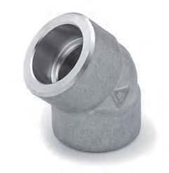
68 FORGED STEEL FITTINGS THREADED 90 ELBOWS - THREADED - B16.11 Rating Dims 1/8 1/4 3/8 1/2 3/ elbows B C LB T 3,18 3,18 3,18 3,18 3,18 3,68 3,89 4,01 4,27 5,61 5,99 6,55 Appt Wt 0,08 0,08 0,11 0,23 0,28 0,46 0,80 1,00 1,60 2,30 4,35 10,25 Kg B C LB T 3,18 3,30 3,51 4,09 4,32 4,98 5,28 5,56 7,14 7,65 8,84 11,18 Appt Wt 0,14 0,14 0,27 0,37 0,60 1,08 1,22 2,45 2,50 5,25 7,40 13,00 Kg B C LB T 6,35 6,60 6,98 8,15 8,53 9,93 10,59 11,07 12,09 15,29 16,64 18,67 App Wt 0,31 0,31 0,50 0,69 1,25 1,65 2,75 3,22 6,25 10,00 17,00 18,00 Kg 45 ELBOWS - THREADED - B16.11 Rating Dims 1/8 1/4 3/8 1/2 3/ elbows B C LB T 3,18 3,18 3,18 3,18 3,18 3,68 3,89 4,01 4,27 5,61 5,99 6,55 App Wt 0,10 0,10 0,11 0,21 0,24 0,39 0,70 0,85 1,23 3,00 3,50 9,00 Kg B C LB T 3,18 3,30 3,51 4,09 4,32 4,98 5,28 5,56 7,14 7,65 8,84 11,18 App Wt 0,13 0,13 0,25 0,36 0,53 0,78 1,02 1,70 2,35 5,40 6,00 10,50 Kg B LB C T 6,35 6,60 6,98 8,15 8,53 9,93 10,59 11,07 12,09 15,29 16,64 18,67 App Wt 0,25 0,25 0,35 0,60 0,95 1,22 1,35 2,55 5,60 8,00 15,50 13,00 Kg


69 THREADED FORGED STEEL FITTINGS TEES - THREADED - B16.11 Tees Equal and reducing Rating Dims 1/8 1/4 3/8 1/2 3/ B C LB T 3,18 3,18 3,18 3,18 3,18 3,68 3,89 4,01 4,27 5,61 5,99 6,55 App Wt 0,12 0,12 0,18 0,29 0,39 0,55 0,93 1,30 1,80 3,00 5,50 14,00 Kg B C LB T 3,18 3,30 3,51 4,09 4,32 4,98 5,28 5,56 7,14 7,65 8,84 11,18 App Wt 0,21 0,21 0,31 0,49 0,80 1,31 1,61 3,20 3,55 6,50 9,25 17,00 Kg B LB C T 6,35 6,60 6,98 8,15 8,53 9,93 10,59 11,07 12,09 15,29 16,64 18,67 App Wt 0,41 0,41 0,60 0,94 1,59 2,14 3,39 4,50 10,00 13,00 19,50 18,00 Kg CROSSES - THREADED - B16.11 Crosses Rating Dims 1/8 1/4 3/8 1/2 3/ B C LB T 3,18 3,18 3,18 3,18 3,18 3,68 3,89 4,01 4,27 5,61 5,99 6,55 App Wt 0,14 0,14 0,19 0,34 0,42 0,75 1,15 1,45 2,25 4,50 7,15 15,00 Kg B C LB T 3,18 3,30 3,51 4,09 4,32 4,98 5,28 5,56 7,14 7,65 8,84 11,18 App Wt 0,22 0,22 0,40 0,63 0,99 1,63 1,97 3,70 4,90 10,50 11,50 21,70 Kg B C LB T 6,35 6,60 6,98 8,15 8,53 9,93 10,59 11,07 12,09 15,29 16,64 18,67 App Wt 0,45 0,45 0,70 1,16 1,80 2,50 4,10 5,20 12,30 14,00 25,00 23,00 Kg
70 FORGED STEEL FITTINGS THREADED COUPLINGS - THREADED - B16.11 Rating Dims 1/8 1/4 3/8 1/2 3/ Couplings Equal & Reducing A LB B App Wt 0,05 0,05 0,06 0,14 0,20 0,39 0,73 1,03 1,35 2,30 3,15 5,80 Kg A LB B App Wt 0,10 0,10 0,12 0,37 0,45 1,00 1,65 1,85 2,80 4,00 5,50 10,00 Kg HALF COUPLINGS - THREADED - B16.11 Rating Dims 1/8 1/4 3/8 1/2 3/ Half Couplings A LB B 16,0 17,5 19,0 24,0 25,5 30,0 33,5 39,5 43,0 46,0 54,0 60,5 Appt Wt 0,02 0,03 0,03 0,07 0,11 0,20 0,37 0,51 0,66 1,15 1,57 2,90 Kg A LB B 16,0 17,5 19,0 24,0 25,5 30,0 33,5 39,5 43,0 46,0 54,0 60,5 App Wt 0,04 0,05 0,06 0,19 0,23 0,50 0,83 0,92 1,40 2,00 2,75 5,00 Kg CAPS - THREADED - B16.11 Rating Dims 1/8 1/4 3/8 1/2 3/ Caps A LB B 19,0 25,0 25,0 32,0 37,0 41,0 44,0 44, ,0 65,0 68,0 T 4,8 4,8 4,8 6,4 6,4 9,7 9,7 11,2 12,7 15,7 19,0 22,4 Appt Wt 0,04 0,05 0,06 0,13 0,21 0,37 0,60 0,73 1,10 2,31 3,00 4,50 Kg A LB B 27,0 27,0 33,0 38,0 43,0 46,0 48,0 51,0 64,0 68,0 75,0 T 6,4 6,4 7,9 7,9 11,2 11,2 12,7 15,7 19,0 22,4 28,4 App Wt 0,16 0,20 0,29 0,40 0,70 1,10 1,35 2,10 3,50 4,80 7,50 Kg


 Square Head Rating Dims 1/8 1/4 3/8 1/2 3/4 1 1 1 4 1 1 2 2 2 1 2 3 4 A 10 11 13 14 16 19 21 21 22 27 28 32 3000 LB B 6 6 8 10 11 13")
71 THREADED FORGED STEEL FITTINGS STREET ELBOWS - MALE/ FEMALE - THREADED - B16.11 Rating Dims 1/8 1/4 3/8 1/2 3/ B C LB T 3,18 3,30 3,51 4,09 4,32 4,98 5,28 5,56 7,14 App Wt 0,13 0,23 0,33 0,53 0,94 1,30 1,47 2,30 Kg B C LB T 5,08 5,66 6,98 8,15 8,53 9,93 10,59 11,07 12,09 App Wt Kg NOTE: At manufacturer option, the dimensions C of the table for threaded Tees (previous page) may be used instead of C in above table Welding Boss WELDING BOSS - THREADED - BS3799 Rating Dims 1/8 1/4 3/8 1/2 3/ A LB B LB B App Wt 0,20 0,24 0,30 0,37 0,50 0,80 1,29 1,78 Kg (6000lb) SQUARE HEAD PLUG (ASME B16.11) Square Head Rating Dims 1/8 1/4 3/8 1/2 3/ A LB B C LB App Wt 0,01 0,02 0,03 0,05 0,09 0,17 0,27 0,40 0,60 0,89 1,25 3,10 Kg


72 FORGED STEEL FITTINGS THREADED PIPE NIPPLES - THREADED - BS3799 1/8 1/4 3/8 1/2 3/ Length L Pipe wall: End Types 100 mm is our standard, but any length will be provided on request. Available in any standard Schedule, e.g. Sch lb, SchXXS lb. Threaded, bevelled or plain. 3000lbs - XS 0,07 0,08 0,11 0,16 0,22 0,31 0,44 0,53 0,74 1,12 1,46 2, lbs - XXS 0,25 0,36 0,54 0,77 0,95 1,31 2,00 2,65 4,00 ROUND HEAD PLUG - THREADED - B16.11 Rating Dims 1/8 1/4 3/8 1/2 3/ LB A D E LB App Wt 0,04 0,05 0,07 0,13 0,22 0,32 0,50 0,72 1,35 2,20 3,30 6,00 Kg HEXAGON HEAD PLUG - THREADED - B16.11 Rating Dims 1/8 1/4 3/8 1/2 3/ LB A H LB F A App Wt 0,02 0,03 0,05 0,07 0,13 0,22 0,41 0,49 0,77 1,61 1,94 4,50 Kg UNIONS - THREADED - BS3799 (1974) Rating Dims 1/8 1/4 3/8 1/2 3/ B - at flats A B LB C D App Wt 0,14 0,17 0,21 0,31 0,49 0,83 1,22 1,53 2,30 5,00 6,25 - A Kg A 44,5 44,5 50,8 60,5 57,2 57,2 76,2 88,9 108,0 108,0 127,0 - B 39,6 39,6 42,9 53,8 58,4 73,2 79,2 88,9 120,7 152,4 190, LB C 22,4 22,4 26,9 26,9 26,9 34,8 34,8 34,8 47,8 53,8 50,8 - D 23,9 23,9 31,8 36,6 44,5 55,6 63,5 76,2 88,9 108,0 127,0 - App Wt 0,20 0,30 0,50 1,12 1,60 2,15 2,42 4,73 6,50 9,50 19,20 - NOTE: The 6000 lbs is typical manufacturer standard - not included in BS3799
73 THREADED FORGED STEEL FITTINGS UNIONS - MALE X FEMALE (MF), THREADED X 2, THREADED + SOCKET WELDED Rating Dims 1/8 1/4 3/8 1/2 3/ A 49,5 54,1 60,7 65,0 72,6 83,1 90,7 99,6 111,3 B 32,0 32,0 36,1 42,9 50,0 59,9 70,1 78,0 95, LB C 16,0 18,0 19,1 21,1 23,9 24,9 29,0 30,0 37,1 D 17,0 19,1 22,1 30,0 36,1 40,9 50,0 59,9 70,1 App Wt 0,16 0,21 0,27 0,46 0,61 0,99 1,55 1,9 2,9 Kg HEXAGON HEAD BUSHING - THREADED - B16.11 Rating Dims 1/8 1/4 3/8 1/2 3/ A LB B F LB Av App 0,02 0,03 0,06 0,10 0,17 0,33 0,42 0,62 1,27 1,65 3,10 Wt Kg HEXAGON NIPPLES - THREADED - BS3799 Rating Dims 1/8 1/4 3/8 1/2 3/ B BS3799 (min) C LB D LB D H App Wt 0,02 0,03 0,06 0,08 0,15 0,24 0,37 0,45 H - AT FLATS Kg NOTE: Reducing sizes is also available, but not included in above table CLOSE TAPER NIPPLES 1 8 1/4 3/8 1/2 3/ Standard 19,1 25,4 28,6 31,8 38,1 44,5 50,8 50,8 50,8 60,3 76,2 88,9 L Length Available in any Standard Production Schedule Wall Thickness, e.g. Sch 40, 80, 160, XXS


74 FORGED STEEL FITTINGS THREADED/SOCKET WELD SWAGED NIPPLES Large end 3/8 1/2 3/ dimensions Length NOTE: 3000 lbs minimum from thickness Sch80, 6000 lbs from thickness Sch160 / XXS respectively for plain vs screwed 90 ELBOWS - SOCKET WELD - B16.11 Rating Dims 1/8 1/4 3/8 1/2 3/ A 11,0 11,0 13,5 15,5 19,0 22,5 27,0 32,0 38,0 41,0 57,0 66,5 B min 10,8 14,2 17,6 21,8 27,2 33,9 42,7 48,8 61,2 73,9 89,8 115,2 B max 11,2 14,6 18,0 22,2 27,6 34,3 43,1 49,2 61,7 74,4 90,3 115, LB C min 3,18 3,30 3,50 4,09 4,27 4,98 5,28 5,54 6,04 7,67 8,30 9,35 D min 6,1 8,5 11,8 15,0 20,2 25,9 34,3 40,1 51,7 61,2 76,4 100,7 D max 7,6 10,0 13,3 16,6 21,7 27,4 35,8 41,6 53,3 64,2 79,4 103,8 E 9,5 9,5 9,5 9,5 12,5 12,5 12,5 16,0 16,0 16,0 16,0 19,0 App Wt 0,08 0,08 0,12 0,24 0,29 0,48 0,75 0,95 1,65 2,50 4,30 9,70 90 elbow Kg A 11,0 13,5 15,5 19,0 22,5 27,0 32,0 38,0 41, B min 10,8 14,2 17,6 21,8 27,2 33,9 42,7 48,8 61, B max 11,2 14,6 18,0 22,2 27,6 34,3 43,1 49,2 61, C min 3,43 4,01 4,37 5,18 6,04 6,93 6,93 7,80 9, D min 3,2 5,6 8,4 11,0 14,8 19,9 28,7 33,2 42, LB E 4,8 7,1 9,9 12,5 16,3 21,5 30,2 34,7 43, E 9,5 9,5 9,5 9,5 12,5 12,5 12,5 12,5 16, App W 0,15 0,17 0,30 0,43 0,66 1,14 1,60 2,70 2, Kg


75 SOCKET WELD FORGED STEEL FITTINGS 45 ELBOWS - SOCKET WELD - B16.11 Rating Dims 1/8 1/4 3/8 1/2 3/ A 8,0 8,0 8,0 11,0 13,0 14,0 17,5 20,5 25,5 28,5 32,0 41,0 B min 10,8 14,2 17,6 21,8 27,2 33,9 42,7 48,8 61,2 73,9 89,8 115,2 B max 11,2 14,6 18,0 22,2 27,6 34,3 43,1 49,2 61,7 74,4 90,3 115,7 C min 3,18 3,30 3,50 4,09 4,27 4,98 5,28 5,54 6,04 7,67 8,30 9, LB D min 6,1 8,5 11,8 15,0 20,2 25,9 34,3 40,1 51,7 61,2 76,4 100,7 D max 7,6 10,0 13,3 16,6 21,7 27,4 35,8 41,6 53,3 64,2 79,4 103,8 E 9,5 9,5 9,5 9,5 12,5 12,5 12,5 12,5 16,0 16,0 16,0 19,0 App Wt 0,08 0,08 0,10 0,19 0,38 0,38 0,58 0,83 1,15 2,05 3,40 9,00 Kg A 8,0 8,0 11,0 12,5 14,0 17,5 20,5 25,5 28, B min 10,8 14,2 17,6 21,8 27,2 33,9 42,7 48,8 61, B max 11,2 14,6 18,0 22,2 27,6 34,3 43,1 49,2 61, C min 3,43 4,01 4,37 5,18 6,04 6,93 6,93 7,80 9, LB D min 3,2 5,6 8,4 11,0 14,8 19,9 28,7 33,2 42, D max 4,8 7,1 9,9 12,5 16,3 21,5 30,2 34,7 43, E 9,5 9,5 9,5 9,5 12,5 12,5 12,5 12,5 16, App Wt 0,12 0,12 0,24 0,30 0,53 0,86 1,07 1,90 2, Kg TEES - EQUAL & REDUCING - SOCKET WELD - B16.11 Rating Dims 1/8 1/4 3/8 1/2 3/ A 11,0 11,0 13,5 15,5 19,0 22,5 27,0 32,0 38,0 41,0 57,0 66,5 B min 10,8 14,2 17,6 21,8 27,2 33,9 42,7 48,8 61,2 73,9 89,8 115,2 B max 11,2 14,6 18,0 22,2 27,6 34,3 43,1 49,2 61,7 74,4 90,3 115, LB C min 3,18 3,30 3,50 4,09 4,27 4,98 5,28 5,54 6,04 7,67 8,30 9,35 D min 6,1 8,5 11,8 15,0 20,2 25,9 34,3 40,1 51,7 61,2 76,4 100,7 D max 7,6 10,0 13,3 16,6 21,7 27,4 35,8 41,6 53,3 64,2 79,4 103,8 E 9,5 9,5 9,5 9,5 12,5 12,5 12,5 12,5 16,0 16,0 16,0 19,0 App Wt 0,12 0,12 0,19 0,31 0,40 0,58 0,91 1,25 2,10 3,15 5,25 13,50 Kg A 11,0 13,5 15,5 19,0 22,5 27,0 32,0 38,0 41, B min 10,8 14,2 17,6 21,8 27,2 33,9 42,7 48,8 61, B max 11,2 14,6 18,0 22,2 27,6 34,3 43,1 49,2 61, LB C min 3,43 4,01 4,37 5,18 6,04 6,93 6,93 7,80 9, D min 3,2 5,6 8,4 11,0 14,8 19,9 28,7 33,2 42, D max 4,8 7,1 9,9 12,5 16,3 21,5 30,2 34,7 43, E 9,5 9,5 9,5 9,5 12,5 12,5 12,5 12,5 16, App Wt 0,21 0,21 0,40 0,56 0,91 1,41 1,75 3,56 4, Kg


76 FORGED STEEL FITTINGS SOCKET WELD CROSSES - SOCKET WELD - B16.11 Rating Dims 1/8 1/4 3/8 1/2 3/ A 11,0 11,0 13,5 15,5 19,0 22,5 27,0 32,0 38,0 41,0 57,0 66,5 B min 10,8 14,2 17,6 21,8 27,2 33,9 42,7 48,8 61,2 73,9 89,8 115,2 B max 11,2 14,6 18,0 22,2 27,6 34,3 43,1 49,2 61,7 74,4 90,3 115,7 C min 3,18 3,30 3,50 4,09 4,27 4,98 5,28 5,54 6,04 7,67 8,30 9, LB D min 6,1 8,5 11,8 15,0 20,2 25,9 34,3 40,1 51,7 61,2 76,4 100,7 D max 7,6 10,0 13,3 16,6 21,7 27,4 35,8 41,6 53,3 64,2 79,4 103,8 E 9,5 9,5 9,5 9,5 12,5 12,5 12,5 12,5 16,0 16,0 16,0 19,0 App Wt 0,14 0,14 0,21 0,34 0,47 0,80 1,25 1,50 2,23 3,95 6,50 16,00 Kg A 11,0 13,5 15,5 19,0 22,5 27,0 32,0 38,0 41, B min 10,8 14,2 17,6 21,8 27,2 33,9 42,7 48,8 61, B max 11,2 14,6 18,0 22,2 27,6 34,3 43,1 49,2 61, C min 3,43 4,01 4,37 5,18 6,04 6,93 6,93 7,80 9, LB D min 3,2 5,6 8,4 11,0 14,8 19,9 28,7 33,2 42, D max 4,8 7,1 9,9 12,5 16,3 21,5 30,2 34,7 43, E 9,5 9,5 9,5 9,5 12,5 12,5 12,5 12,5 16, App Wt 0,26 0,26 0,50 0,67 1,06 1,79 2,15 4,45 5, Kg UNIONS - SOCKET WELD - BS3799 Rating Dims 1/8 1/4 3/8 1/2 3/ A B 10,7 14,1 17,6 21,8 27,4 34,1 42,9 49,0 61,0 73,8 89,7 C 3,2 3,3 3,5 4,1 4,3 5,0 5,3 5,6 6,1 7,7 8, LB D 6,8 9,2 12,5 15,5 21,0 26,5 35,0 40,5 52,0 62,0 78,0 E 3,2 3,2 3,2 4,0 4,8 4,8 5,6 5,6 6,4 9,6 12,7 F S App Wt 0,14 0,18 0,23 0,39 0,52 0,73 1,20 1,56 2,30 5,00 7,15 Kg NOTE: 6000 lbs is available with manufacturer standard dimensions
77 SOCKET WELD FORGED STEEL FITTINGS REDUCING INSERT 3000LB - SOCKET WELD Type 1 NB C D A B E F Type Type 2 Type 3 1/2 x 3/8 47,0 17,5 10,9 23,9 25,9 1 1/2 x 1/4 47,0 14,0 9,4 16,0 2 3/4 x 1/2 26,9 21,6 12,4 25,4 32,0 1 3/4 x 3/8 26,9 17,5 10,9 14,0 2 3/4 x 1/4 26,9 14,0 9,4 16,0 22,1 3 1 x 3/4 33,5 27,2 14,5 28,4 38,1 1 1 x 1/2 33,5 21,6 12,4 20,6 2 1 x 3/8 33,5 16,5 10,9 22,1 25,9 3 1 x 1/4 33,5 14,0 9,4 23,9 22, x 1 42,4 33,8 16,0 32,0 45, x 3/4 42,4 27,2 14,5 20, x 1/2 42,4 21,6 12,4 22,1 32, x ,4 42,5 17,5 33,0 56, x 1 48,4 33,8 16,0 20, x 3/4 48,4 27,2 14,5 22,1 38, x 1/2 48,4 21,6 12,4 24,1 32,0 3 2 x ,6 48,8 19,1 20,6 2 2 x ,6 42,7 17,5 22,1 56,9 3 2 x 1 60,6 33,8 16,0 24,1 45,0 3 2 x 3/4 60,6 27,2 14,5 25,4 38,1 3 2 x 1/2 60,6 21,6 12,4 26,9 32,0 3 COUPLING & HALF COUPLING - SOCKET WELD - B16.11 Rating Dims 1/8 1/4 3/8 1/2 3/ A 6,5 6,5 6,5 9,5 9,5 12,5 12,5 12,5 19,0 19,0 19,0 19,0 Coupling B min 10,8 14,2 17,6 21,8 27,2 33,9 42,7 48,8 61,2 73,9 89,8 115,2 B max 11,2 14,6 18,0 22,2 27,6 34,3 43,1 49,2 61,7 74,4 90,3 115,7 C min 3,18 3,30 3,50 4,09 4,27 4,98 5,28 5,54 6,04 7,67 8,30 9, LB D min 6,1 8,5 11,8 15,0 20,2 25,9 34,3 40,1 51,7 61,2 76,4 100,7 D max 7,6 10,0 13,3 16,6 21,7 27,4 35,8 41,6 53,3 64,2 79,4 103,8 E 9,5 9,5 9,5 9,5 12,5 12,5 12,5 12,5 16,0 16,0 16,0 19,0 F 16,0 16,0 17,5 22,5 24,0 28,5 30,0 32,0 41,0 43,0 44,5 48,0 App Wt 0,05 0,05 0,07 0,11 0,15 0,26 0,37 0,42 0,77 1,10 1,40 2,35 Kg Half Coupling A 6,5 6,5 6,5 9,5 9,5 12,5 12,5 12,5 19, B min 10,8 14,2 17,6 21,8 27,2 33,9 42,7 48,8 61, B max 11,2 14,6 18,0 22,2 27,6 34,3 43,1 49,2 61, C min 3,43 4,01 4,37 5,18 6,04 6,93 6,93 7,80 9, LB D min 3,2 5,6 8,4 11,0 14,8 19,9 28,7 33,2 42, D max 4,8 7,1 9,9 12,5 16,3 21,5 30,2 34,7 43, E 9,5 9,5 9,5 9,5 12,5 12,5 12,5 12,5 16, F 16,0 16,0 17,5 22,5 24,0 28,5 30,0 32,0 41, App Wt 0,07 0,07 0,10 0,15 0,34 0,37 0,49 0,68 1, Kg

78 FORGED STEEL FITTINGS SOCKET WELD CAPS -SOCKET WELD - B16.11 Rating Dims 1/8 1/4 3/8 1/2 3/ B min 10,8 14,2 17,6 21,8 27,2 33,9 42,7 48,8 61,2 73,9 89,8 115,2 B max 11,2 14,6 18,0 22,2 27,6 34,3 43,1 49,2 61,7 74,4 90,3 115, LB C min 3,18 3,30 3,50 4,09 4,27 4,98 5,28 5,54 6,04 7,67 8,30 9,35 E 9,5 9,5 9,5 9,5 12,5 12,5 12,5 12,5 16,0 16,0 16,0 19,0 H 4,8 4,8 4,8 6,4 6,4 9,6 9,6 11,2 12,7 15,7 19,0 22,4 App Wt 0,03 0,04 0,06 0,14 0,18 0,30 0,51 0,65 0,92 1,40 2,50 3,50 Kg B min 10,8 14,2 17,6 21,8 27,2 33,9 42,7 48,8 61, B max 11,2 14,6 18,0 22,2 27,6 34,3 43,1 49,2 61, LB C min 3,43 4,01 4,37 5,18 6,04 6,93 6,93 7,80 9, E 9,5 9,5 9,5 9,5 12,5 12,5 12,5 12,5 16, H 6,4 6,4 6,4 7,9 7,9 11,2 11,2 12,7 15, App Wt 0,08 0,08 0,14 0,18 0,21 0,46 0,70 0,89 1, Kg Welding Boss WELDING BOSS - SOCKET WELD.- BS3799 Rating Dims 1/8 1/4 3/8 1/2 3/ B 10,7 14,1 17,6 21,8 27,4 34,1 49,0 61, LB C 3,2 3,3 3,5 4,1 4,3 5,0 5,6 6, LB C ,2 6,1 7,0 7,8 9,5 D THROUGH BORE, Sch lb, Sch lb F 28, S App Wt 0,20 0,23 0,29 0,38 0,53 0,83 1,31 1,86 Kg
79 THREADS FORGED STEEL FITTINGS TAPER PIPE THREADS, NPT Diameter of Diameter of Nomi- Outside Num- the pitch of the pitch of Efficient Length Increase nal diameter ber Pitch the bolt at the bolt at length of the of the size of the of the outside the inside of the hand diameter of tube threads end of the end of the thread packing per rotation tube per thread thread D inch P Eo E1 L2 L1 mm In. mm In. mm In. mm In. mm In. mm In. mm In ,29 0, ,94 0, ,233 0, ,489 0,3736 6,703 0,2639 4,102 0,1615 0,0586 0, ,72 0, ,411 0, ,126 0, ,487 0, ,205 0,4018 5,786 0,2278 0,0881 0, ,14 0, ,411 0, ,545 0, ,929 0, ,358 0,4078 6,096 0,24 0,0881 0, ,34 0, ,814 0, ,264 0, ,772 0, ,556 0,5337 8,128 0,32 0,1132 0, ,67 1, ,814 0, ,579 0, ,117 0, ,86 0,5457 8,61 0,339 0,1132 0, ,4 1, ,209 0, ,826 1, ,461 1, ,343 0, ,16 0,4 0,1379 0, ,16 1, ,209 0, ,551 1, ,218 1, ,952 0, ,668 0,42 0,1379 0, ,26 1, ,209 0, ,621 1, ,287 1, ,377 0, ,668 0,42 0,1379 0, ,32 2, ,209 0, ,633 2, ,325 2, ,215 0, ,074 0,436 0,1379 0, ,02 2, ,175 0,125 69,076 2, ,159 2, ,892 1, ,322 0,682 0,1983 0, ,9 3,5 8 3,175 0,125 84,852 3, ,068 3, ,48 1,2 19,456 0,766 0,1983 0, , ,175 0,125 97,472 3, ,776 3, ,75 1,25 20,853 0,821 0,1983 0, ,3 4,5 8 3,175 0, ,093 4, ,433 4, ,02 1,3 21,437 0,844 0,1983 0,00781 NOTE: All sizes in the table correspond to the ASME B and API 5 L Standards, excepted for the nominal sizes 1/8 and 1/4 for which E1 and L1 are not measured on the same plane according to API 5L. However, these sizes are the same when brought on the same plane.


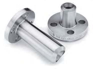
80 O-LETS
81 O-LETS BRANCH OUTLETS O LETS. BASIS FOR DESIGN OF O LETS: MANUFACTURER STANDARD: The O lets in this catalogue are based on a single manufacturer s standard design and denominations. The standard design is based on ASME B31.3, but O lets may be designed, manufactured and verified to other requirements at the client s request. HEIGHT STANDARDISATION: The table-listed heights (A) of reducing weldolets buttweld, socket weld and threaded outlets are identical to the heights standardised in MSS SP-97, except the 3000lbs socket weld outlets in sizes 2 ½ 4. However, it should be noted that the height stated as standard may have to be changed due to the actual/ specific design required for specific size/ wall thickness combinations. DESIGN OPTIMISATION: O lets may be designed and manufactured to the customer s specific design requirements, i.e. O lets can be designed design to specific design parameters (e.g. PCS) and/ or Norsok EDS NOL1 so as to reduce the welding required in the crotch area. DESIGN DETAILS REQUIRED FOR OPTIMISATION OF O LETS: DESIGN VERIFICATION: Drawings and calculations for each individual O let may be provided, if requested by the client at the enquiry stage. DIMENSION UNIFICATION: O lets may also be designed to fit a range of run header dimensions i.e., each O let will be suitable for use on various header pipe sizes. This design will, however, require more welding during fabrication, as the O let dimensions cannot be optimised to a specific size and the actual design parameters. TYPES OF O LETS
82 O-LETS Ready to Weld Every fitting is shaped to fit the pipe and it self-aligning. butt-welding of the branch pipe for shop or field fabrication. Layout The template is the inside of the fitting. Cut Hole The hole in the run pipe on reducing sizes can be cut out either before or after the fitting is welded on. The hole can be cut with a torch, a drill or a hole saw. Welding the fitting to the run pipe prior to cutting the hole helps prevent distortion on the run and can be done generally on outlet sizes over two inches. «Space» for Welding The Weldolet is raised off run pipe to establish proper weld gap by placing spacers, e.g. welding rods, under the fitting. This provides a uniform welding gap between the curvature of the run and base of fitting. Tack Weld The base joint is tack welded, prefer ably at four points, each half way between the crotch and skirt sections of the fitting. The spacers are then removed. Stringer Bead The stringer bead is applied completely around the base of the fitting. The established weld gap ensures full penetration. Reinforcing Beads Reinforcing welds should be made at the crotch bevel areas of the fitting to provide maximum weld at the crotchtapering to minimu at the skirt. Particular care should be taken to weld only the bevel portion of the fitting. (See «weld lines» on above drawing) This eliminates the unnecessary use of continuous passes and prevents the erroneous practice of welding up to the rib on the skirt portion of the fitting. A continuous cover bead should be added to fill the bevel and provide a smooth tapered weld. EXAMPLE OF WELD SEQUENCE Longitudinal Section Fig. 1 Wide bases or footings at crotch section distribute internal and external stresses. Gradual changes of section eliminate stress concentration. Funnel shaped opening provides improved flow conditions. The outlet is machine bevelled for quick easy Transverse Section Fig. 2 Note the blending of the skirt section of the Weldolet to the run pipe to avoid abrupt change in intersection. Throat of weld at this point is designated by the welding bevel.
83 O-LETS DIMENSIONS UNIFICATION In order to reduce warehouse inventory, our outlets have been unified to fit on different run-pipe sizes with gap maximum of 1/32 between the run-pipe and outlet. This does not cause any problems during welding x 3 4 STD A105 FH6 BUTTWELD-OUTLETS, STANDARD AND EXTRA STRONG, SOCKET-OUTLETS & THREADED-OUTLETS 3000LBS. OUTLET SIZE RUN PIPE SIZES Outlet over 4 order to specific run-pipe size BUTTWELD-OUTLETS SCH. 160 AND XXS OUTLET SIZE RUN PIPE SIZES Outlet over 2 order to specific run-pipe size BUTTWELD-OUTLETS & THREADED-OUTLETS 6000LBS. OUTLET SIZE RUN PIPE SIZES

84 O-LETS BUTTWELD OUTLETS - STANDARD REDUCED SIZES FULL SIZES OUTLET SIZE A C Approx. A C D Approx. [inch] [mm] [mm] Weight [mm] [mm] [mm] Weight 1/2 19,0 24,0 0,1 19,0 24,0 15,8 0,1 3/4 22,2 30,0 0,1 22,2 30,0 21,0 0,1 1 27,0 36,5 0,3 27,0 36,5 26,6 0, ,5 44,5 0,4 31,5 44,5 35,0 0, ,4 51,0 0,5 33,4 51,0 40,9 0,4 2 38,0 65,0 0,8 38,0 65,0 52,5 0, ,2 76,2 1,1 41,2 76,2 62,8 1,0 3 44,5 93,5 1,8 44,5 93,5 78,0 1, ,5 112,6 2,5 47,5 112,6 90,2 2,3 4 51,0 120,5 2,9 51,0 120,5 102,2 3,1 5 57,0 141,3 4,7 57,0 141,3 128,2 3,9 6 60,3 170,0 6,5 60,3 170,0 154,0 6,7 8 69,8 220,5 10,7 69,8 220,5 202,5 13, ,0 274,0 18,0 78,0 274,0 254,0 16, ,0 324,0 27,0 86,0 324,0 304,5 27, ,0 356,0 30,0 89,0 356,0 336,5 32,0 BUTTWELD OUTLETS - EXTRA STRONG REDUCED SIZES FULL SIZES OUTLET SIZE A C Approx. A C D Approx. [inch] [mm] [mm] Weight [mm] [mm] [mm] Weight ,0 24,0 0,1 19,0 24,0 13,9 0, ,2 30,0 0,1 22,2 30,0 18,9 0,1 1 27,0 36,5 0,2 25,4 36,5 24,3 0, ,5 44,5 0,4 28,5 44,5 32,8 0, ,4 51,0 0,5 31,5 51,0 38,1 0,4 2 38,0 65,0 0,8 38,0 65,0 49,3 0, ,2 76,2 1,2 41,2 76,2 59,0 1,2 3 44,5 93,5 1,9 44,5 93,5 73,7 1, ,5 112,6 2,6 47,5 112,6 85,4 2,3 4 51,0 120,5 3,0 51,0 120,5 97,2 3,5 5 57,0 141,3 4,8 57,0 141,3 122,3 4,3 6 78,0 170,0 10,5 78,0 170,0 146,3 6,8 8 98,5 220,0 17,0 98,5 220,0 194,0 14, ,0 265,0 21,0 95,3 265,0 247,5 21, ,0 316,0 28,0 100,0 320,0 298,0 28, ,0 351,0 32,0 105,5 355,0 330,0 34,5

![[inch] [mm] [mm] Weight [mm] [mm] Weight 1 2 28,5 14,3 0,1 28,5 14,3 0,1 3 4 31,5 19,0 0,3 31,5 19,0 0,3 1 38,0 25,5 0,4 38,0 25,5 0,4 1 1 4 44,5 33,4 0,6 44,5 33,4 0,6 1 1 2 50,7 38,0 0,8 50,7 38,0](/docs-images/99/141077620/images/85-1.jpg "0,8 2 55,5 42,9 1,0 55,5 42,9 1,0 2 1 2 61,8 53,9 1,6 61,8 53,9 1,6 3 73,0 73,0 2,9 73,0 73,0 2,9 4 84,0 98,4 4,8 84,0 98,4 4,8 5 93,5 122,2 6,5 93,5 122,2 6,5 6 104,7 146,0 12,8 104,7 146,0 13,8")
85 O-LETS REDUCED SIZES FULL SIZES OUTLET SIZE A C Approx. A C Approx. [inch] [mm] [mm] Weight [mm] [mm] Weight ,5 14,3 0,1 28,5 14,3 0, ,5 19,0 0,3 31,5 19,0 0,3 1 38,0 25,5 0,4 38,0 25,5 0, ,5 33,4 0,6 44,5 33,4 0, ,7 38,0 0,8 50,7 38,0 0,8 2 55,5 42,9 1,0 55,5 42,9 1, ,8 53,9 1,6 61,8 53,9 1,6 3 73,0 73,0 2,9 73,0 73,0 2,9 4 84,0 98,4 4,8 84,0 98,4 4,8 5 93,5 122,2 6,5 93,5 122,2 6, ,7 146,0 12,8 104,7 146,0 13,8 OUTLET REDUCED SIZES FULL SIZES SIZE A C F G Approx. A C D F G Approx. [inch] [mm] [mm] [mm] [mm] Weight [mm] [mm] [mm] [mm] [mm] Weight 1/2 25,5 24,0 31,8 10,0 0,1 25,5 22,4 16,0 31,8 10,0 0,1 3/4 27,0 30,0 36,6 13,0 0,2 27,0 30,0 21,0 36,6 13,0 0,1 1 33,4 36,5 46,1 13,0 0,3 33,4 36,5 26,7 46,1 13,0 0, ,4 44,5 55,6 13,0 0,4 33,4 44,5 35,0 55,6 13,0 0, ,8 51,0 62,0 13,0 0,5 34,8 51,0 40,9 62,0 13,0 0,4 2 38,0 65,0 74,7 16,0 0,7 38,0 65,0 52,5 74,7 16,0 0, ,0 76,2 87,4 16,0 1,3 46,0 76,2 62,8 87,4 16,0 1,0 3 50,7 93,5 104,8 16,0 1,7 50,7 93,5 77,9 104,8 16,0 1, ,8 101,5 122,3 19,0 2,0 53,3 112,8 90,1 117,5 19,0 2,0 4 57,0 120,5 130,2 19,0 3,3 55,5 127,0 102,2 130,2 19,0 3,0 OUTLET REDUCING SIZES SIZE A C F G Approx. [inch] [mm] [mm] [mm] [mm] Weight ,5 19,0 40,0 10,0 0, ,5 25,5 46,0 13,0 0,4 1 39,6 33,4 57,2 13,0 0, ,0 38,0 65,1 13,0 0, ,7 49,3 76,3 13,0 0,9 2 52,1 70,0 92,1 16,0 2,4

86 O-LETS OUTLET REDUCED SIZES FULL SIZES SIZE A C F Approx. A C D F Approx. [inch] [mm] [mm] [mm] Weight [mm] [mm] [mm] [mm] Weight ,5 24,0 31,8 0,1 25,5 24,0 16,0 3l,80 0, ,0 30,0 36,6 0,2 27,0 30,0 20,7 36,6 0,1 1 33,4 36,5 46,1 0,3 33,4 36,5 27,0 46,1 0, ,4 44,5 55,6 0,4 33,4 44,5 34,9 55,6 0, ,8 51,0 62,0 0,5 34,8 51,0 41,2 62,0 0,4 2 38,0 65,0 74,7 0,8 38,0 65,0 52,4 74,7 0, ,0 76,2 87,4 1,4 46,0 76,2 63,5 87,4 1,1 3 50,7 93,5 104,8 2,0 50,7 93,5 77,8 104,8 2, ,8 101,5 122,3 2,6 53,3 112,8 90,5 117,5 2,1 4 57,0 120,5 130,2 3,2 55,5 120,5 103,2 130,2 3,1 OUTLET REDUCING SIZES SIZE A C F Approx. [inch] [mm] [mm] [mm] Weight ,5 19,0 40,0 0, ,5 25,5 46,0 0,4 1 39,6 33,4 57,2 0, ,0 38,0 65,1 0, ,7 49,3 76,3 0,9 2 52,1 70,0 92,1 2,3
87 O-LETS Elbow Outlet Dimensions for all three styles are the same except for the D dimension on the butt welding outlet which matches the proper schedule on the branch pipe LBS THREADED AND SOCKETWELD STANDARD AND EXTRA STRONG BUTT-WELD 6000 LBS THREADED AND SOCKETWELD SCHEDULE 160 AND DOUBLE EXTRA STRONG BUTT-WELD Nominal Nominal Outlet DIMENSIONS WEIGHT Elbow Size Elbow Size Size lb 6000lb 3000 lb 6000lb 3000 lb 6000lb 3000 lb 6000lb (Inch) (Inch) Inches C C D D E E Approx. Wt. Approx.Wt lb 6000 lb mm mm mm mm mm mm Kg. Kg ,1 38,1 31,8 31,8 38,1 38,1 0,23 0, ,1 38,1 31,8 31,8 38,1 38,1 0,23 0, ,1 43,6 31,8 35,7 38,1 45,2 0,30 0, ,6 54,0 35,7 45,2 45,2 54,4 0,34 0, ,0 73,0 45,2 54,8 52,4 55,6 0,52 1, ,0 79,4 54,8 63,5 55,6 58,8 0,86 1, ,4 106,4 63,5 82,6 58,8 69,9 1,20 2, ,4-82,6-69,9-2,39 -
88 O-LETS Lateral Outlet Dimensions for all three styles are the same except for the D dimension on the butt welding outlet which matches the proper schedule on the branch pipe LBS THREADED AND SOCKETWELD STANDARD AND EXTRA STRONG BUTT-WELD 6000 LBS THREADED AND SOCKETWELD SCHEDULE 160 AND DOUBLE EXTRA STRONG BUTT-WELD Nominal Nominal Outlet DIMENSIONS WEIGHT Elbow Size Elbow Size Size lb 6000lb 3000 lb 6000lb 3000 lb 6000lb 3000 lb 6000lb (Inch) (Inch) Inches C C D D E E Approx. Wt. Approx. Wt lb 6000 lb (mm) (mm) (mm) (mm) (mm) (mm) Kg. Kg ,5 36,5 31,8 31,8 39,7 39,7 0,23 0, ,5 36,5 31,8 31,8 39,7 39,7 0,23 0, ,5 43,6 31,8 35,7 39,7 47,6 0,30 0, , ,7 45,2 47,6 57,2 0,34 0, ,5 45,2 54,8 57,2 61,9 0,52 1, ,5 76,2 54,6 63,5 61,9 66,7 0,86 1, ,2 104,8 63,5 82,6 66,7 81,0 1,20 2, ,8-82, ,29 - NOTE: Other Outlet sizes available on request.

89 O-LETS FLANGED NIPPLE OUTLETS The height (A) is 150mm for all sizes, except # that is 165mm.The bore (F) equals the nominal bore of the branch pipe. FLANGED NIPPLE OUTLET - 150# Outlet size B E C C Type Std/XS 160/XXS 1 1/2 88,9 11,2 24,0 14,3 1 3/4 98,6 12,7 30,0 19, ,0 14,3 36,5 25, ,5 15,9 44,5 33, ,0 17,5 51,0 38, ,4 19,1 65,0 42,9 1 FLANGED NIPPLE OUTLET - 300# Outlet size B E C C Type Type Std/XS 160/XXS Std/XS 160/XXS 1/2 95,3 14,3 24,0 14, /4 117,5 15,9 30,0 19, ,8 17,5 36,5 25, ,4 19,0 44,5 33, ,6 20,6 51,0 38, ,1 22,2 65,0 42,9 1 2 FLANGED NIPPLE OUTLET - 600# Outlet size B E C C Type Type Std/XS 160/XXS Std/XS 160/XXS 1/2 95,3 20,7 24,0 14, /4 117,5 22,3 30,0 19, ,8 23,9 36,5 25, ,4 27,0 44,5 33, ,6 28,6 51,0 38, ,1 31,8 65,0 42,9 1 2 FLANGED NIPPLE OUTLET - 900# /1500# Outlet size B E C C Type Type Std/XS 160/XXS Std/XS 160/XXS 1/2 120,7 28,6 24,0 14, /4 130,2 31,8 30,0 19, ,2 35,0 36,5 25, ,8 35,0 44,5 33, ,8 38,1 51,0 38, ,9 44,5 65,0 42,9 2 2 FLANGED NIPPLE OUTLET # Outlet size B E C C Type Std/XS 160/XXS 1/2 133,4 36,6 24,0 14,3 2 3/4 139,7 38,1 30,0 19, ,8 41,3 36,5 25, ,2 44,5 44,5 33, ,2 50,8 51,0 38, ,0 57,2 65,0 42,9 2

 equals the nominal bore of the branch pipe.")
90 O-LETS FLANGED BUTTWELD OUTLET Flanged Buttweld Outlet is available also for larger sizes than listed below (up to 24 for 150# to 1500#). Flanged Buttweld Outlet is available in all pressure classes - below listed 150# and 2500# are typical - others available at request. The dimensions below are based on RF type flanges. Other facings may be supplied at request. The C dimensions listed are based on Std wall for header and branch pipe. Any wall may be supplied at request. The bore (F) equals the nominal bore of the branch pipe. FLANGED BUTTWELD OUTLET - 150# FLANGED BUTTWELD OUTLET # Outlet Outlet size B E A C Type size B E A C Type 1/2 88,9 11,2 65,0 24,0 1 3/4 98,6 12,7 75,0 30, ,0 14,3 85,0 36, ,5 15,9 90,0 44, ,0 17,5 95,0 51, ,4 19,1 105,0 65, ,8 22,3 112,0 76, ,5 23,8 115,0 93, ,9 23,8 120,0 112, ,6 23,8 130,0 120, ,0 23,8 146,0 141, ,4 25,4 150,0 170, ,9 28,6 175,0 220, ,4 30,2 180,0 274, ,6 31,8 200,0 324,0 1 1/2 133,4 36,5 100,0 24,0 2 3/4 139,7 38,1 110,0 30, ,8 41,3 125,0 36, ,2 44,5 135,0 44, ,2 50,8 150,0 51, ,0 57,2 170,0 65, ,7 63,5 190,0 76, ,8 73,0 220,0 93, ,6 82,6 250,0 120, ,1 98,4 290,0 141, ,6 114,3 340,0 170, ,5 133,4 395,0 220, ,1 171,5 505,0 274, ,0 190,5 555,0 324,0 2 NIPPLE OUTLET / 6000 LB Available with plain / bevel / threaded end Outlet size A C C 3000 lb 6000lb 1/2 89,0 24,0 14,5 3/4 89,0 30,0 19,0 1 89,0 36,5 25, ,0 44,5 33, ,0 51,0 38,0 2 89,0 65,0 43,0
91 O-LETS INSERT BRANCH OUTLET Insert Branch Outlets are available for any header wall thickness. The below dimensions are applicable for header wall thickness up to and including XS. Outlet size A Min. header pipe size 1/2 32, /4 32, , ,0 2 Other dimensions , available at 2 44,0 3 specific request 3 51, , , , , , , , , , ,0 30

92 WEIGHTS
Materialvalg sett fra en leverandør
 Materialvalg sett fra en leverandør Ifea 13. desember 2011 Jon Harald Pedersen Agenda Bakgrunn Eksempler Bolter Design trykk Tubing & fittings Håndratt Instrumentering på ventilen TR2212 materialkrav Omfang
RF Power Capacitors Class1. 5kV Discs
 RF Power Capacitors Class 5kV Discs T H E C E R A M C E X P E R T S RF Power Capacitors Class 5kV Discs The CeramTec Group is a world leader in the design and manufacture of complex electronic ceramic
Hydal Aluminium legeringer Hydal Aluminium alloys
 Sammenligning ere med brukte tidligere nasjonale brukte standarder nasjonale standarder Hydro Hydal Aluminium d related alloys international and related international designation designation Hydal Hydro
RF Power Capacitors Class kV Discs with Moisture Protection
 RF Power Capacitors Class 0-20kV Discs with Moisture Protection T H E C E R A M I C E X P E R T S RF Power Capacitors Class 0-20kV Discs with Moisture Protection The CeramTec Group is a world leader in
RF Power Capacitors Class , 20 & 30 mm Barrel Transmitting Types
 RF Power Capacitors Class 2.7, 20 & 30 mm Barrel Transmitting Types T H E C E R A M I C E X P E R T S RF Power Capacitors Class 2.7, 20 & 30 mm Barrel Transmitting Types The CeramTec Group is a world leader
Parker Hannifin AS. Making parts and systems all over the world
 Parker Hannifin AS Making parts and systems all over the world Parker Hannifin Corp. 2007 FY07 omsetning NOK. 57 milliarder 9 divisjoner 8 400 distributører 57 000 ansatte 900 000 produkt nummer 417 000
Cylindrical roller bearings
 Cylindrical roller bearings Cylindrical roller bearings 292 Definition and capabilities 292 Series 292 Variants 293 Tolerances and clearances 294 Design criteria 296 Installation/assembly criteria 297
Hydal Aluminium legeringer Hydal Aluminium alloys
 ± Hydal Aluminium legeringer Hydal Aluminium alloys Sammenligning Sammenligning med tidligere med brukte tidligere nasjonale brukte standarder nasjonale standarder Hydro Aluminium Hydro Sammenligning Hydal
Merak Un-glazed Porcelain Wall and Floor Tiles
 6 Colours 3 es Absolute Collection 7 s Merak Un-glazed Porcelain Wall and Floor Tiles Merak includes seven sizes perfectly designed for seamless installation. 600 x 50mm 600 x 100mm 600 x 300mm 600 x 150mm
Hydal Aluminium legeringer Hydal Aluminium alloys
 ± Hydal Aluminium legeringer Hydal Aluminium alloys Sammenligning Sammenligning med tidligere Sammenligning brukte med tidligere nasjonale med brukte standarder tidligere nasjonale brukte standarder nasjonale
Product Facts. Product code example
 ESAM Smoke control damper for multi Rectangular smoke control damper ESAM is specifically designed for use in multi fire compartment applications as a closing or as an opening damper for smoke extract
Sveiste stålrør Welded steel pipes EN 10217
 Sveiste stålrør Welded steel pipes EN 027 H.R. SANVOL Materiale: P235R Foringsrør/pelerør. Standard lengde 3,0m. Faset 30/45 i en ende. Material: P235R Steel pipes for casing/piling. Standard length 3,0m.
RESCO PART # DESCRIPTION MFR MODEL # MANUFACTURER ERMCO Transformer 1.5KVA 7200 CONV SB 2 POS 120/240 NT 103-Y ERMCO
 TRANSFORMERS TRANSFORMERS ERMCO Single-Phase Pole-Mounted Distribution Transformer Designed and manufactured in compliance with all applicable ANSI, RUS and DOE standards. All transformers are oil filled,
TRANSFORMERS WESTERN UNITED ELECTRIC SUPPLY
 WESTERN UNITED ELECTRIC SUPPLY Single-Phase Pole-Mounted Distribution Transformer Designed and manufactured in compliance with all applicable ANSI, RUS and DOE standards. All transformers are oil filled,
C C A Stainless Steel A F593/F594 Stuffing Box A. Stuffing Box O-Ring/gasket C/F594. Grade Grade
 KENNEDY VALVE KS-RW RESILIENT WEDGE VALVES KENNEDY VALVE AWWA C515 Resilient Wedge Gate Valves Meet or Exceed the Requirements of AWWA Standard C515 UL-262/FM-1120/1130 ULC-Underwriters of Canada 2 1/2
Steatite Interlocking Beads. Steatite Band heater (Regular) Steatite Band Heater (Small) Steatite Band Heater (Large)
 Steatite Band Heater (Small) Steatite Band Heater (Large)") INDEX 1 2 3 4 5 6 7 8 9 10 11 12 13 14 15 16 17 18 Steatite Interlocking Beads Steatite Band heater (Regular) Steatite Band Heater (Small) Steatite Band Heater (Large) Steatite Band Heater (Extra Large)
INDEX 1 2 3 4 5 6 7 8 9 10 11 12 13 14 15 16 17 18 Steatite Interlocking Beads Steatite Band heater (Regular) Steatite Band Heater (Small) Steatite Band Heater (Large) Steatite Band Heater (Extra Large)
WEDGE GATE VALVE PRESSURE SEAL BONNET
 WEDGE GATE VALVE PRESSURE SEAL BONNET BABCOCK VALVES VAL 2 3 BABCOCK VALVES VAL 1 BODY Available both in cast and forged steel, it has been designed to meet all the requirements of ASME, API and British
Cylindrical roller bearings
 Cylindrical roller bearings Cylindrical roller bearings 292 Definition and capabilities 292 Series 292 Variants 293 Tolerances and clearances 294 Design criteria 296 Installation/assembly criteria 297
Monteringsprosedyre for Soundstop - lydmatte
 NORSOK STANDARD PIPING AND EQUIPMENT INSULATION R-004 5.7 Guidelines for acoustic insulation The acoustic pipe insulation classes can be met by various combinations of insulation materials and jacketing
Smart High-Side Power Switch BTS730
 PG-DSO20 RoHS compliant (green product) AEC qualified 1 Ω Ω µ Data Sheet 1 V1.0, 2007-12-17 Data Sheet 2 V1.0, 2007-12-17 Ω µ µ Data Sheet 3 V1.0, 2007-12-17 µ µ Data Sheet 4 V1.0, 2007-12-17 Data Sheet
PrO-ASTM Centrifuges. Centurion. C1015 Micro Prime Centrifuge. A Micro that offers: Oil testing. Petroleum testing, ASTM methods
 PrO-ASTM Centrifuges Oil testing. Petroleum testing, ASTM methods C1015 Micro Prime Centrifuge C1015. (230V 50/60Hz). 1.C1015. (110V 60Hz) Speed Rcf Max Timer Dims HWD Weight Power Memory Accel rates Decel
Edge Of Dock Leveler. Size: Widths 66, 72, 78, 84. Lengths 15, 17 Lips. Capacities: 20,000 25,000 30,000 35,000 NEVERLIFT NL
 Edge Of Dock Leveler Size: Widths 66, 72, 78, 84 Lengths 15, 17 Lips Capacities: 20,000 25,000 30,000 35,000 NEVERLIFT NL-7220-15 Who Uses EOD Levelers LTL trucking Companies with dedicated Truck Fleets
Rotagrip Ltd Tel 0044 (0) Website FOR VPC-TYPE. Speed Max R.P.M. Speed Max R.P.M.
 Website FOR VPC-TYPE. Speed Max R.P.M. Speed Max R.P.M.") Light Duty Live Center Center is made of SCM420 alloy steel by heat treatment to provide higher rigidity wear-resistance. Center is constituted by ball bearings assembly. Applicable to middle-speed & high-speed
Light Duty Live Center Center is made of SCM420 alloy steel by heat treatment to provide higher rigidity wear-resistance. Center is constituted by ball bearings assembly. Applicable to middle-speed & high-speed
Model Description. Portfolio Performance
 Model Description Market timing results from 2000 to 2019 are based on our Market Allocation Algorithm holding the top two (2) ranked assets each month. Risk control is added to keep asset(s) in cash if
LIFT PROGRAMME SLIDING GUIDES 10/2015
 2 SLIDING GUIDES 1! B C D E F @ G H I J K L M N J O O I P M J Q N R S M T U V E W @ " #!! " $ % & ' < = > >? @ A A ' 9 : ; ; 4 4 0 3 1 0 /. - ) * +,, ) * +,, 8 8 7 6 5 ) * +,, ( ( ( ( X ( ( 5 Guide holders
STOREFRONTS. Typical Details SCREW RACE JOINERY. Center Glazed Series B1. Interior Glazing (Shown with FF400 subsill) April 1998
 April 1998") - SCREW RCE JOINERY NOTE: NP22 glazing gaskets are used on both sides of glass. Typical TYPICL ELEVTION / (2.) HC20 Optional Head nchor PS00 Optional Filler EC0 Subsill s End Closure Typical (0.) IS IS2
- SCREW RCE JOINERY NOTE: NP22 glazing gaskets are used on both sides of glass. Typical TYPICL ELEVTION / (2.) HC20 Optional Head nchor PS00 Optional Filler EC0 Subsill s End Closure Typical (0.) IS IS2
Recommended machine weight:
 0 00 00 VIEW ( : 0 ) VIEW0 ( : 0 ) CLOSED OPEN 0 FOR HYDRULIC PCKGE: TESS ORDER NO.: GE0-HYDRULIC PRTS GENERL TOLERNCES MCHINED PRTS: NS-ISO - NS-EN ISO 0. Linear measurements class:. ngle measurements
Data Sheet for Joysticks
 Available with Potentiometers or Hall sensors Several handle options Small size at low installation depth The 812 series is available with several different handle options. These small joysticks are recommended
Den europeiske byggenæringen blir digital. hva skjer i Europa? Steen Sunesen Oslo,
 Den europeiske byggenæringen blir digital hva skjer i Europa? Steen Sunesen Oslo, 30.04.2019 Agenda 1. 2. CEN-veileder til ISO 19650 del 1 og 2 3. EFCA Guide Oppdragsgivers krav til BIMleveranser og prosess.
Data Sheet for Joysticks
 Available with Potentiometers or Hall sensors Several handle options Small size at low installation depth The 812 series is available with several different handle options. These small joysticks are recommended
Slope-Intercept Formula
 LESSON 7 Slope Intercept Formula LESSON 7 Slope-Intercept Formula Here are two new words that describe lines slope and intercept. The slope is given by m (a mountain has slope and starts with m), and intercept
Data Sheet for Joysticks
 Contactless Hall Sensors Optionally with Pushbutton function in handle Mounting option Threaded housing Waterproof, IP class 68 (1 metre) / IP69K The TRY14 series offers proportional miniature-size thumb
AVS MAGMA SOLENOID VALVES
 8 AVS Ing. J.C. Römer GmbH Reismühle 3 3D-98 Grafenau E-Mail: info@avs-roemer.com MAGMA the valve principle from AVS-Römer Medium separated MEDIUM SEPARATED Lever actuated seat valve with separating membrane
Software applications developed for the maritime service at the Danish Meteorological Institute
 Software applications developed for the maritime service at the Danish Meteorological Institute Anne Marie Munk Jørgensen (ammj@dmi.dk), Ove Kjær, Knud E. Christensen & Morten L. Mortensen Danish Meteorological
RF Power Capacitors Class kV Discs
 RF Power Capacitors Class 0-5kV Discs Morgan Advanced Materials is a world leader in the design and manufacture of complex electronic ceramic components and assemblies used in a wide range of applications
Data Sheet for Joysticks
 2 axes (special versions with 3 Axes upon request) Spring return to center position or friction hold Customer-specific handles and sensors upon request Angle-dependent Actuation of Microswitches The 830
Relevante standarder og utfordringer ifm design av målesystemer
 Relevante standarder og utfordringer ifm design av målesystemer Date: 15.03.2014 Rev.: 01 Stig Norheim Referanser (sitat) Illustrasjoner fra NFOGM sin hjemmeside (Metering School) Selskapskvav Norsok Måleforskriften
Data Sheet for Joysticks
 Up to 3 axes Spring return, friction clutch optionally Sealed up to IP63 Multifunction handle for additional functions, e.g. switches, rockers, deadman paddle Also available with USB- or CAN-Bus-Interface
WINN. HiSeal høytytende spjeldventiler gir effektiv to-veis lukking over et bredt spekter av driftsforhold. HiSeal spjeldventil med høy ytelse
 WINN HiSeal høytytende spjeldventiler gir effektiv to-veis lukking over et bredt spekter av driftsforhold. Egenskaper Positiv lukking som oppnås mekanisk og som ikke er avhengig av assistanse fra rørtrykket.
RF Power Capacitors Class1 5kV Discs
 RF Power Capacitors Class 5kV Discs Morgan Advanced Materials is a world leader in the design and manufacture of complex electronic ceramic components and assemblies used in a wide range of applications
Monteringsanvisning Installation manual Taksokkel for LHH og CareLite Ceiling mount for LHH and CareLite
 Monteringsanvisning Installation manual Taksokkel for LHH og CareLite Ceiling mount for LHH and CareLite Art.nr. 05-900-573-00. Page 1 of 9 Norsk Monteringsanvisning taksokkel Denne monteringsmanualen
Rustfrie kaldvalsede plater
 Rustfrie kaldvalsede plater Kvalitet EN 1.4301, tilsv. AISI304 - SS2333, Overflate 2B Gruppe 6000. 0.40 1000 2000 3.20 6.40 84.70 63.50 52.90 42.40 0.50 1000 2000 4.00 8.00 80.70 60.50 50.40 40.40 0.60
2018 ANNUAL SPONSORSHIP OPPORTUNITIES
 ANNUAL SPONSORSHIP OPPORTUNITIES MVP SPONSORSHIP PROGRAM CALLING ALL VENDORS! Here is your chance to gain company exposure while strengthening your dealer Association at the same time. Annual Sponsorship
RF Power Capacitors Class1 : 10kV Discs
 RF Power Capacitors Class : 0kV Discs Morgan Advanced Materials is a world leader in the design and manufacture of complex electronic ceramic components and assemblies used in a wide range of applications
RF Power Capacitors Class kV Discs with Moisture Protection
 RF Power Capacitors Class 0-20kV Discs with Moisture Protection Morgan Advanced Materials is a world leader in the design and manufacture of complex electronic ceramic components and assemblies used in
PSi Apollo. Technical Presentation
 PSi Apollo Spreader Control & Mapping System Technical Presentation Part 1 System Architecture PSi Apollo System Architecture PSi Customer label On/Off switch Integral SD card reader/writer MENU key Typical
ANKERKJETTING TEKNOLOGIUTVIKLING OG OPERASJONELLE UTFORDRINGER
 ANKERKJETTING TEKNOLOGIUTVIKLING OG OPERASJONELLE UTFORDRINGER Authors: Jonathan Fernandez, Vicinay Cadenas S.A. Hans-Jürgen Henk, Vicinay Cadenas Northern Europe Speaker: Hans-Jürgen Henk Produksjonsanlegget
Trykkrør/pumpeledning
 VA Trykkrør/pumpeledning VA Trykkrør/pumpeledning PVC trykkrør SDR og trykklasser, PVC SDR and MOP (Max. Operating Pressure), Dim. Dimensjonerende Brudd- Design SDR SDR SDR spenning spenning faktor 34,4
Marmi Plus One. Sleek, Essential, Stunning
 MARMI PLUS ONE Marmi Plus One Sleek, Essential, Stunning Marmi Plus One Bianco - DME01 90x90 cm Marmi Plus One Bianco - DME01 60x120 cm Marmi Plus One Bianco MATTE Marmi Plus One Bianco - DME01 60x120
CTGA Meeting February 2, 2012
 CTGA Meeting February 2, 2012 Outline Product Family Machine Issues Emission Standards Future Developments Product Family Commander Johnson Star I-Star Vine Diverter Commander 2002 Heavy Duty Wheel Motors
Det teknisk- naturvitenskapelige fakultet
 Det teknisk- naturvitenskapelige fakultet SUBJECT: BIB 120 KONSTRUKSJONSMEKANIKK 1 DATE: September 5, 2012 TIME: AID: 15:00 19:00 (4 hours) Authorized calculator, Dictionary (English-Norwegian) and drawing
Skjema for spørsmål og svar angående: Skuddbeskyttende skjold Saksnr TED: 2014/S
 Skjema for spørsmål og svar angående: Skuddbeskyttende skjold Saksnr. 201300129 TED: 2014/S 017-026835 Nr Dokument Referanse Svar 1 Kvalifikasjonsgrunnlag Er det mulig å få tilsendt Nei 27.01.2014 27.01.2014
ALUMINUM TWIN STACK PORTABLE AIR COMPRESSOR OL50135AL OPERATOR S MANUAL
 OL50135AL OPERATOR S MANUAL ALUMINUM TWIN STACK PORTABLE AIR COMPRESSOR! WARNING: To reduce the risk of injury, the user must read and understand the Operator s Manual before using this product. IN619302AV
TRAPPETA RN MONTERINGSANVISNING
 [Skriv inn tekst] TRAPPETA RN MONTERINGSANVISNING 3 x 1,6 m Trappetårn Monteringsveiledningen er laget for å gi en beskrivelse på monteringen av Delta TRAPPETÅRN. Delta TRAPPETÅRN er typegodkjent under
TUNNEL LIGHTING. LED Lighting Technology
 TUNNEL LIGHTING TunLite Linear Designed LED Tunnel & Underpass Light The TunLite is an LED linear luminaire providing reliable solutions to cover the lighting requirements of tunnels and underpasses. It
Slide 1. The World of Temperature
 Slide 1 The World of Temperature Hvorfor Temperature Måling?! Temperatur er det mest prukte måleprinsippet i prosessindustrien Temperature : Pressure = 7 : 1 Temperature : Flow = 14 : 1 Temperature : Level
STILLAS - STANDARD FORSLAG FRA SEF TIL NY STILLAS - STANDARD
 FORSLAG FRA SEF TIL NY STILLAS - STANDARD 1 Bakgrunnen for dette initiativet fra SEF, er ønsket om å gjøre arbeid i høyden tryggere / sikrere. Både for stillasmontører og brukere av stillaser. 2 Reviderte
DC/AC inverters DC/AC invertere
 DC/AC inverters DC/AC invertere Mascot range of DC/AC inverters Using a 12V or 24V battery, these inverters are ideal for applications such TV, video, smaller household appliances, and tools for camping,
Statens vegvesen. Rekkverket har en totalbredde på 0,54m og høyde på 0,90m (uten kantdrager). LT 102 er testet med en lengde på ca. 60m.
. LT 102 er testet med en lengde på ca. 60m.") Statens vegvesen Linetech GmbH & Co. KG Von-Hünefeld-Straße 99 50829 Köln Birgit Schenk Behandlende enhet: Saksbehandler/telefon: Vår referanse: Deres referanse: Vår dato: Vegdirektoratet Matteo Pezzucchi
Statens vegvesen Linetech GmbH & Co. KG Von-Hünefeld-Straße 99 50829 Köln Birgit Schenk Behandlende enhet: Saksbehandler/telefon: Vår referanse: Deres referanse: Vår dato: Vegdirektoratet Matteo Pezzucchi
Product Change Notice
 Product Change Notice Alternate site qualified for assembly of assembly of Device Engineering Inc. small outline integrated circuit (SOIC) packages. Change of lead finish from Tin Lead SnPb to Nickel Palladium
Statens vegvesen. Testene tilfredsstiller kravene til styrkeklasse T3 med en målt arbeidsbredden på 0,7m.
 Statens vegvesen DELTA BLOC International GmbH Industriestrasse 28 2601 Sollenau Østerrike Paul Bittner Behandlende enhet: Saksbehandler/telefon: Vår referanse: Deres referanse: Vår dato: Vegdirektoratet
(see table on right) 1,500,001 to 3,000, ,001pa to 250,000pa
 1,500,001 to 3,000, ,001pa to 250,000pa") UNDERWRITING LIMITS The following tables show our financial and medical underwriting limits effective from 07 July 2017. FINANCIAL LIMITS Protection Financial evidence requirements Additional financial
UNDERWRITING LIMITS The following tables show our financial and medical underwriting limits effective from 07 July 2017. FINANCIAL LIMITS Protection Financial evidence requirements Additional financial
Superclamp. Bruksanvisning Nr.015 for. Generelt om sikker bruk av løfteredskap:
 Bruksanvisning Nr.015 for Superclamp Generelt om sikker bruk av løfteredskap: Sikker bruk av løfteredskap forutsetter at løfteredskapet er sertifisert og godkjent i henhold til forskrift om Maskiner Best.nr.522,
Statens vegvesen. Godkjenning av LT 103 vegrekkverk. Linetech GmbH & Co. KG Von-Hünefeld-Straße Köln Tyskland
 Statens vegvesen Linetech GmbH & Co. KG Von-Hünefeld-Straße 99 50829 Köln Tyskland Behandlende enhet: Saksbehandler/telefon: Vår referanse: Deres referanse: Vår dato: Vegdirektoratet Matteo Pezzucchi /
RF Power Capacitors Class1
 RF Power Capacitors Class 2.7, 20 & 30mm Doorknob/Barrel Transmitting Types Morgan Advanced Materials is a world leader in the design and manufacture of complex electronic ceramic components and assemblies
(see table on right) 1,500,001 to 3,000, ,001pa to 250,000pa
 1,500,001 to 3,000, ,001pa to 250,000pa") UNDERWRITING LIMITS The following tables show our financial and medical underwriting limits effective from 11 April 2016. FINANCIAL LIMITS Protection Financial evidence requirements Additional financial
UNDERWRITING LIMITS The following tables show our financial and medical underwriting limits effective from 11 April 2016. FINANCIAL LIMITS Protection Financial evidence requirements Additional financial
EG-leder konferanse 2017
 09.11. 2017 EG-leder konferanse 2017 PER-ARNE RØSTADSAND, LEDER SEKTORSTYRET PETROLEUM I STANDARD NORGE Sektorstyret petroleum i Standard Norge -Leder -Nestleder 2 Standard Norge NORSOK OG INTERNASJONAL
SEVERE DUTY GENERAL PURPOSE Three-Phase TEFC. Features that make a difference: Standard Features:
 SEVERE DUTY GENERAL PURPOSE Three-Phase TEFC Efficiency motors offer high performance with maximum energy efficiency. This motor provides high efficiency and low cost of ownership throughout the entire
EGENSKAPER ANVENDELSE. Technical data sheet ESCR - KONSTRUKSJONSSKRUE TIL TRE
 ESCR er en skrue med diameter 8 eller 10 mm. Den har et skivehode som er designet til å sammenføye to eller flere trebjelker. ESCRskruene har en type 17 spiss, som griper raskt, og en freseribbe som sikrer
Rockhopper and Spacers Bobbins Stoppeskiver / Steel Discs Låseskiver / Stopwashers Trekant Børtre / Triangle Yoke. Dører / Doors
 2.0 Tråltyper / Trawl 2.1 Sorteringssystem / Sorting Systems 2.2 Sekker / Cod Ends 2.3 Lin - Nett / Nets Slitematter / Protcetion Net Labbetuss 2.4 Kuler / Floats 2.5 2.6 2.7 2.8 Gear Rockhopper and Spacers
Data Sheet for Joysticks
 Different handle designs available Optionally with Pushbuttons and Deadman Industrial-suited robust design IP classes up to 68 (on request) Several Output Options (analog, CAN J1939, CANopen, USB) The
2.0 Tråltyper / Trawl... side 4 2.1 Sorteringssystem /... side 10 Sorting Systems 2.2 Sekker / Cod Ends... side 12 2.3 Lin - Nett / Nets...
 2.0 Tråltyper / Trawl... side 4 2.1 Sorteringssystem /... side 10 Sorting Systems 2.2 Sekker / Cod Ends... side 12 2.3 Lin - Nett / Nets... side 13 Slitematter / Protcetion Net Labbetuss 2.4 Kuler / Floats...
Passenger Terminal World Expo 2011 Copenhagen, Denmark. Steven B. Cornell Assoc. Vice President
 Passenger Terminal World Expo 2011 Copenhagen, Denmark Steven B. Cornell Assoc. Vice President Overview PRT Definition Planning Parameters for Airport Projects Speed Capacity Geometrics Costs New Airport
Frode Endresen. Installasjonskrav ved fiskal gassmåling Hvorfor anbefales stadig de mest konservative løsningene?
 Frode Endresen Installasjonskrav ved fiskal gassmåling Hvorfor anbefales stadig de mest konservative løsningene? Ultralyd gassmåler Vært på markedet siden siste del av nittitallet Befestet sin posisjon
Statens vegvesen. Rekkverket har en totalbredde på 0,54m og høyde på 0,90m (uten kantdrager).
.") Statens vegvesen Likelydende brev - se vedlagt liste Behandlende enhet: Saksbehandler/telefon: Vår referanse: Deres referanse: Vår dato: Vegdirektoratet Matteo Pezzucchi / 22073246 15/212577-15 07.12.2015
Statens vegvesen Likelydende brev - se vedlagt liste Behandlende enhet: Saksbehandler/telefon: Vår referanse: Deres referanse: Vår dato: Vegdirektoratet Matteo Pezzucchi / 22073246 15/212577-15 07.12.2015
2A September 23, 2005 SPECIAL SECTION TO IN BUSINESS LAS VEGAS
 2A September 23, 2005 SPECIAL SECTION TO IN BUSINESS LAS VEGAS SPECIAL SECTION TO IN BUSINESS LAS VEGAS 3A September 23, 2005 SEE, PAGE 8A Businesses seek flexibility. It helps them compete in a fast-paced,
REMOVE CONTENTS FROM BOX. VERIFY ALL PARTS ARE PRESENT READ INSTRUCTIONS CAREFULLY BEFORE STARTING INSTALLATION
 2011-2014 FORD EXPLORER PARTS LIST Qty Part Description Qty Part Description 1 Bull Bar 2 12mm x 35mm Bolt Plates 1 Passenger/Right Mounting Bracket 2 12mm Nut Plate 1 Driver/Left Mounting Bracket 2 12mm
Statens vegvesen. Rekkverket med føringsskinne av type A er i utgangspunktet samme egenskaper som det som var fullskalatestet, type B.
 Statens vegvesen Stalprodukt S.A ul. Wygoda 69, 32-700 Bochnia Polen Dawid Barnaś Behandlende enhet: Saksbehandler/telefon: Vår referanse: Deres referanse: Vår dato: Vegdirektoratet Matteo Pezzucchi /
Water terminals SYSDUCT HP. Ductable fan coil unit
 Water terminals SYSDUCT HP Ductable fan coil unit SYSDUCT HP Ductable fan coil unit The ductable air treatment units are available in 7 sizes. Units are extremely suitable for small centralized conditioning
Statens vegvesen. Rekkverket med føringsskinne av type A er i utgangspunktet samme egenskaper som det som var fullskalatestet, type B.
 Statens vegvesen Stalprodukt S.A ul. Wygoda 69, 32-700 Bochnia Polen Dawid Barnaś Behandlende enhet: Saksbehandler/telefon: Vår referanse: Deres referanse: Vår dato: Vegdirektoratet Matteo Pezzucchi /
Original NiTO Couplings Original NiTO Koblinger. NiTO Industrial Spray Guns NiTO Industri Spulepistoler
 Original NiTO Couplings Original NiTO Koblinger NiTO Industrial Spray Guns NiTO Industri Spulepistoler NiTO Leading supplier of high quality couplings for the professional market NiTO kvalitetsmæssigt
Unit Relational Algebra 1 1. Relational Algebra 1. Unit 3.3
 Relational Algebra 1 Unit 3.3 Unit 3.3 - Relational Algebra 1 1 Relational Algebra Relational Algebra is : the formal description of how a relational database operates the mathematics which underpin SQL
Justeringsanvisninger finnes på de to siste sidene.
 d Montering av popup spredere Justeringsanvisninger finnes på de to siste sidene. Link til monteringsfilm på youtube: http://youtu.be/bjamctz_kx4 Hver spreder har montert på en "svinkobling", det vil si
Exercise 1: Phase Splitter DC Operation
 Exercise 1: DC Operation When you have completed this exercise, you will be able to measure dc operating voltages and currents by using a typical transistor phase splitter circuit. You will verify your
OMT Technical Information. Versions OMT. Versions
 Versions Versions Mounting flange Shaft Port size European version US version Drain connection Check valve Low pressure release High pressure release Main type designation Standard Wheel Brake-wheel G
SHORE POWER CONVERTER LIST 2018
 2018 POWER AT YOUR CONTROL Shore cord capacities These tables provide a approximate indication of the amount of kva capacity of different amperage shore cords at common worldwide voltages. Use these tables
PRODUKTKATALOG 2014 OPPDRETTSUTSTYR FISKEREDSKAP SELSTADTAU FLÅTESTASJON INDUSTRI & OFFSHORE. Leverandør til maritim næring PRODUKTKATALOG 2014
 PRODUKTKATALOG 2014 OPPDRETTSUTSTYR FISKEREDSKAP SELSTADTAU FLÅTESTASJON INDUSTRI & OFFSHORE www.selstad.no Leverandør til maritim næring PRODUKTKATALOG 2014 1 LEVERANDØR TIL MARITIM NÆRING Selstad AS
Draft. Schiedel s.r.o. Horoušanská 286, CZ Nehvizdy. Schiedel s.r.o. Modlanská 1, CZ Teplice. Permeter Vent (PMV)
") Permeter Smooth ir Certificate No. 0036 CPD 9195 34-2012 Ytelseserklæring Utstedt I henhold til CPD 89/106/EEC Krav for metallskorstein Del 1 Produkt for skorstein ihht Produsent Fabrikkadresse Produktnavn
Permeter Smooth ir Certificate No. 0036 CPD 9195 34-2012 Ytelseserklæring Utstedt I henhold til CPD 89/106/EEC Krav for metallskorstein Del 1 Produkt for skorstein ihht Produsent Fabrikkadresse Produktnavn
ELSEMA 1, 2, 4-Channel 27MHz Transmitter FMT312E, FMT31202E, FMT31204E
 FMT-312E, FMT-31202E, FMT-31204E 12V 1Watt 27MHz Transmitter Features 3 versions available 1-channel (FMT-312E), 2-channel (FMT- 31202E) and 4-channel (FMT-31204E) 1 Watt Transmitter with current consumption
GIMOTA AG. Assembly Instructions Dataconnectors D-SUB. Datenstecker Katalog Gimota AG 04/14 3
 GIMOTA AG Assembly Instructions Dataconnectors D-SUB 2015 Datenstecker Katalog Gimota AG 04/14 3 1 Assembly Instructions D-SUB TRAC / TRAC H 1.1 Preparation Standard Part sets Standard part sets conclude
Characteristic and Design load resistances based on characteristic bond strengths for hef 4d (minimum embedment) to 20d
 to 20d") PRO V200 VINYLESTER RESIN TECHNICAL DATA Product Description PRO V200 is a two component high strength 10:1 ratio chemical anchoring resin system. It is designed as a fast curing high strength resin fixing
PRO V200 VINYLESTER RESIN TECHNICAL DATA Product Description PRO V200 is a two component high strength 10:1 ratio chemical anchoring resin system. It is designed as a fast curing high strength resin fixing
Accuracy of Alternative Baseline Methods
 Accuracy of Alternative Baseline Methods Dr. Steven Braithwait Christensen Associates Energy Consulting IEPEC - Paris June 2010 Outline Demand response & role of baseline loads Measures of baseline performance
Dynamic Programming Longest Common Subsequence. Class 27
 Dynamic Programming Longest Common Subsequence Class 27 Protein a protein is a complex molecule composed of long single-strand chains of amino acid molecules there are 20 amino acids that make up proteins
Open Burner - 12" 2009 Viking Commercial Division 40
 Open Burner - 12" 2009 Viking Commercial Division 40 V36B6-NG V24B4-NG V12B2-NG Part Number Part Description QTY QTY QTY QTY QTY QTY 1 AV36PS Plate Shelf, Standard 36" 1 1 AV24PS Plate Shelf, Standard
MID-TERM EXAM TDT4258 MICROCONTROLLER SYSTEM DESIGN. Wednesday 3 th Mars Time:
 Side 1 av 8 Norwegian University of Science and Technology DEPARTMENT OF COMPUTER AND INFORMATION SCIENCE MID-TERM EXAM TDT4258 MICROCONTROLLER SYSTEM DESIGN Wednesday 3 th Mars 2010 Time: 1615-1745 Allowed
TK - Value Line 2017 Catalog
 TK - Value Line 2017 Catalog www.pensacolacabinetoutlet.com 1 TK-White Shaker Cab Outlet, LLC TK - Value Line Color Style Sheet All Price List Offer the following: Retail 25% Off Wholesale 35% Off Builder
Emneevaluering GEOV272 V17
 Emneevaluering GEOV272 V17 Studentenes evaluering av kurset Svarprosent: 36 % (5 av 14 studenter) Hvilket semester er du på? Hva er ditt kjønn? Er du...? Er du...? - Annet PhD Candidate Samsvaret mellom
[36] Boiserie. Melamine and lacquered door handles. Optional metal handle. Standard ABS handle. Look _silver (J) Pop _silver (P) _chromed (K)
![[36] Boiserie. Melamine and lacquered door handles. Optional metal handle. Standard ABS handle. Look _silver (J) Pop _silver (P) _chromed (K)](/thumbs/101/149932177.jpg "[36] Boiserie. Melamine and lacquered door handles. Optional metal handle. Standard ABS handle. Look _silver (J) Pop _silver (P) _chromed (K)") BOISERIE Backs 18mm thick matt, scratch resistant, non-reflective and washable melamine particleboard (Mfc), anti-shock ABS edge 1,5mm thick. They are provided with adjustable feet. Backs can be lacquered
BOISERIE Backs 18mm thick matt, scratch resistant, non-reflective and washable melamine particleboard (Mfc), anti-shock ABS edge 1,5mm thick. They are provided with adjustable feet. Backs can be lacquered
G-1 SLIDE GUIDE STROKE BALL SPLINE ROTARY BALL SPLINE BALL SPLINE TOPBALL PRODUCTS SLIDE BUSH SLIDE UNIT SLIDEROTARYBUSH STROKE BUSH SLIDE SHAFT
 ROTARY STROKE G1 Advanced Machining Technology: NB will perform a wide variety of highly accurate machining processes to provide custom shafting from relatively simple machining, such as tapping and shaft